Monday, May 26, 2014

Tuckahoe Plantation, Richmond, Virginia, 1733-50

Update: August, 2023. This post needs revisions

In the last 9 years I have learned a great deal about practical geometry.  I have also read Material Witnesses, Camille Wells' book, published in 2018 by the University of Virginia Press, about domestic architecture in Early Virginia. She writes about Tuckahoe in great detail. 

I will leave this as I wrote it in 2014 until my new drawings are ready for publication. 


I visited Tuckahoe Plantation recently.  I wanted to see more brick work, after studying the walls of Gunston Hall.

The Tuckahoe Plantation Main House has brick end walls on the south wing, c.1733.  HABS has drawings that I could use, even though they are very small: 1/8"= 1'-0"

The  Plantation is on a bluff above the James River.Originally visitors came by boat. I came by car, turning off a narrow road onto a dirt lane lined with trees and pastures for horses and cows. Finally the buildings appeared, and parking for my car.  I liked entering on foot at a slow pace. There are few signs, and no visitors center. I was almost the only person on the grounds and enjoyed it all, even as I was studying the buildings, thinking about them carefully  I hope to go again for a thorough tour of the house (open only by appointment).

The upper photograph is of the south wing facing the James River. The second is the west wall of the south wing.


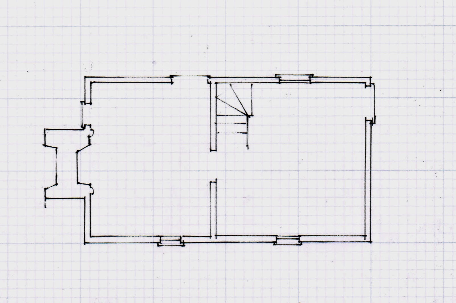
As the floor plan shows the House has two wings joined by a Great Hall. It is also surrounded by stately trees and shrubbery, therefore hard to photograph as a whole. The end walls of the south wing feel much more hand wrought than do the walls of Gunston Hall. There is also a subtle brick pattern, dark and light. The North Wing end walls are not brick.
The foundation (above grade) for the house is brick, but the north wing, added in 1750's does not seem to have a basement - no windows or doors, only vertical slits in the walls. I wondered if this difference, as well as the change in chimney construction, would also be visible in the geometry, whether it represented a change in how the north wing and possibly the Great Hall were considered, laid out, and built.

Here are the diagrams. The geometry does change.

I have drawn 3 green diamonds on the South Wing (They could be 3 squares, same proportions.) To the center one I have overlaid the red square and added the diagonals of the half squares which cross at the walls of the South Hall. The points of the diagonals also determine the window openings. The rooms are not quite square.

Both of the North Wing rooms are square - noted by green squares with their diagonals. The squares divide in thirds - red lines in upper square. Then  a new square - drawn in red - is extended to determine the width of the North Hall.

The Great Hall is 2 squares crossed. I've drawn one in green, the other in red. The space where they cross is the entry, the crossing determined by the squares divided into thirds.

I wondered if the brick end walls would be 3-4-5 triangles, which would be structurally sound. They appear to be - see the green diagonal on the south end wall. The window and door sizes and placements do not neatly fit the pattern.

The Great Hall elevation is crossed squares - in green, just as its plan is. The edges of  the squares mark the edges of the windows. The diagonals' crossings mark the height of the door, the centers of the door panels.

The North Wing end wall is 2 squares - in green, divided in halves and thirds - in red. This also continues the floor plan geometry. The roof pitch comes from  the frame - not quite a 12/12, determined by the geometry, not by numbers.

The North Elevation can be looked at two ways.
On the right I have drawn the square (the diamond which marks the centers of  the square's sides) beginning at grade, including the foundation. The left edge is at the door frame.
On the left side I have drawn a square with its diagonals. The length of the square is the height of the wood frame of the wall of the wing; it does not include the foundation. That square ends at the edge of the paneling for the entrance, which are noted on the floor plan.

I do not know enough about the framing for this house. In the Northeast I have seen and worked on many buildings from this period and have knowledge of standard framing and regional variations. I can show how the geometry determined the framing and therefore the design. I wonder if Tuckahoe's framing changed between 1733 and 1750.


Part of my reason to visit to Tuckahoe was to see its intact measured one and  two room houses that looked in the HABS drawings very much like the houses Henry Glassie wrote about. I will write about that next.

Sunday, May 18, 2014

"The Country Builder's Assistant", by Asher Benjamin, 1797


 Here is the first page of Asher Benjamin's pattern book, printed in Greenfield, Massachusetts in 1797. I show here that page and Plates 25 and 26 from my copy of the 1992 reprint by Applewood Books, Bedford, MA.
The original prints of The Country Builder's Assistant which I've read (available  in rare book libraries) are full of smudges and notes made by their owners. Clearly the books were well used.  200 years old: they feel ready to be used again.

They are quite small, about 5" x 8, so I think the engravings were intended as concepts.
Benjamin says, just above his name on the first page, "with a PRINTED EXPLANATION  to each". But there is none for these plans and elevations. Did he expect that those using his book would need no more explanation to adapt these drawings to their own use? That they, having served apprenticeships with master-builders and joiners, could read the geometry? It has been suggested that these and the church design were after thoughts, dropped in. Perhaps. However in the sequence of the book they come in logical order: after stairs and before roofs.


These are a way to present ideas, not fully realized designs. He draws them causally: no sash in the windows, no framing notations, just a sketch.  Did he use geometry? Yes.


Plate 25
uses the same geometry for plan and elevation - 2 squares crossed.  The width of the hall is determined, 8 1/2  units, the length set: 26 units. Starting from the left and right walls of the hall, one square goes to the right - red solid lines - the other to the left - red dashed lines.  The left front room is square, the back room the left-over space. The right front room - the kitchen with its circular baking oven - is deeper, its size and those of the rear rooms laid out by smaller and smaller squares - see the red dots where the lines cross. I have drawn the diagonals of the half squares for fun because they locate the columns dividing the front hall from the stair hall. -dashed green lines.
The elevation uses the same geometry, crossed squares. I drew them from the base. The space where they cross is the width of the dramatic entrance. If I had started them at the line of the first floor, where the granite blocks give way to clapboard, the squares would have outlined the Palladian window above.
On the right the windows are located on the half and quarter marks of the square - red verticals.  The diagonals of the half squares touch the tips of both sides of the Palladian window. I have marked them in green as well as the squares around the entrance and the  window.
 

Plate 26
A 3 story Federal house - with its characteristic smaller third floor windows, a  balustrade to hide the roof, and a entrance with columns and a fanlight.
There are 2 possible geometries here: 2 crossed squares - shown in red on the elevation - lining up neatly on each side of the entrance - or a square on end in the center - half shown in dashed green, left of center. The focus on the center would be a tentative nod to Palladio.  The windows are set by the center lines - green verticals.

In plan the same choices exist, crossed squares - in green -  or a square in the center overlapping a square of the same size on end (en pointe?)  - in red. Its sides extend beyond the drawing.
The centered square locates the center lines of the windows, the stair hall wall. The crossed squares overlaid on the centered squares locate the head of the stair and the width of the hall - red circles.

 There is more... see the green arrows which show a smaller square within the larger, determining the location of the side windows.

I think Asher Benjamin was having fun: no client to please, no budget, only himself; a quick and neat presentation of ideas on a very small scale where precision didn't matter. I also think his audience could read 'geometry'. It was not a foreign language.  


Thursday, May 15, 2014

a kitchen extension


This 1920's planned neighborhood is on the National Register of Historic Places.
The family asked for enough space so they could bake pies from scratch while talking to their friends. The Japanese maple, to the right in front of the side porch, needed to stay.

The new wing is from the back porch - left - and the 3 windows - middle - to the drain spout -right. The new bulkhead provided better basement access.

A bay already existed on the right side, so I matched the roof pitch. The height of the roof was set by the 2nd floor windows. The windows, both the rough openings of the individual windows and the three together with wide mullions - match other windows in the neighborhood and others in the house itself. The size of the porch helps the windows look centered ( they aren't) on the wall, which helps the extension look simple, expected - "uhh, where's the wing? what else would you have built?"
Of course, none of my work would look nearly as good as it does without the excellent skills of the contractors I work with. They respect my vision. I know they improve what I put on paper.

Tuesday, May 6, 2014

Gunston Hall, Mason Neck, Virginia


updated 5/14/2014

Gunston Hall was built from 1755 to 1759 by George Mason as a home for his family on Mason Neck, Virginia.

Gunston Hall in February, 2014,  photograph by Justin Wilcox, through Wikipedia.

The drawings are from the HABS collection.

Gunston Hall, Return to Splender, the 50 page booklet published by the Board of Regents in 1991, came to me from a friend who knew I would like the pictures, the excellent recounting of the history of the house and its restorations, and the HABS drawings. She was right.

The booklet relates how George Mason began the building himself and then had his brother find and send  William Buckland from England to help him finish the work.

I was intrigued by the fact that George Mason, a very well educated man, realized that he needed help. I wondered if I could see why by looking at the drawings. He knew enough about construction to begin. What happened? Would the expertise William Buckland brought to the work be visible?


George Mason knew about what kind of  plan would fit his family and their life. He knew how to build with stone and brick, how to set a foundation, cap a window, taper a gable, frame a roof. He knew enough geometry to use 3-4-5 triangles and their permutations.

Remember that the diagrams can be enlarged by clicking on them.

The plan  is 4 triangles, or 2 rectangles with 2 sides 3 units long, 2 sides 4 units long. On the right side he has divided the rectangle in half to make his two formal rooms. He has laid out the diagonals of both smaller rectangles. Where they cross he has placed the wall at the edge of the hall.

Note that the rectangles do not meet at the center of the main doors, but to the right side.

The left side of the house was the family dining room and the Masons' own room which Ann Mason also used as office as she managed much of the plantation.

Here a hall separates the rooms.To determine the width George Mason divided the rectangle in half lengthwise and then added the diagonals. The center point is the location of the inside of the wall to the hall. Where the  diagonals cross to the other side of the brick wall, the corridor walls begin. Note that the stair width is also determined by another division of the rectangle and its subsequent diagonals.

On the right side the inside space is divided - it would be smaller than the outside space - into thirds to place the fireplaces in the center of the rooms. I think it is possible that this is one of the changes Buckland made.
Understanding that wall thickness can throw off symmetry comes from experience. Buckland had training as a finish carpenter (a joiner), but he was young, just 22. Mason was 30; he knew brick and mortar, not perhaps not the finer points of symmetry. Proving this supposition would only be possible if the chimney stack was opened and taken apart - not very likely! So this is truly conjecture on my part.


The end elevations continue to use the 3-4-5 triangle for its proportions.
The door is centered. The top of the brick walls is the top of the rectangle.  The gable repeats the triangles. The bricks end on the upper edge. The shape is square and sound, made possible by the 3-4-5 90* triangle which is always true.
I have noted with a strong dot on the upper diagonals how the window height and location are also determined by the diagonal intersections.

Note that the depths of the porches are also 3-4-5 triangles -  drawn in green.


So then to the main elevations, one facing the water, the other the road.

 We already know that the left and right sides of the house are not equal as George Mason wanted larger formal rooms on the right side.

 Here is where I think he got himself in trouble: the left side is truly not as long as the right - see the dotted red line. Look carefully and the dormers: they are balanced but not symmetrical, nor evenly spaced.

 Perhaps Buckland stepped in here, adding the windows on either side of the front door.
What he really did was divert the eye - he added the Gothic porch to the river front: inviting, decorative. with half circles and Gothic curves. We are drawn to the porch and ignore the symmetry.


March 18, 2023: I wrote this almost 9 years ago.  I now know a lot more about Practical Geometry. Please also see my most recent  post about the porch: 

https://www.jgrarchitect.com/2021/07/the-geometry-of-gunston-halls-north.html

I will not delete the following discussion of the porch design. I want a potential geometer to see that as we recover a lost skill we make assumptions and therefore mistakes. That's ok. It's part of the work..


Here and in the house his knowledge of Palladio and what was fashionable in England is obvious. William Buckland knew the classic vocabulary. The booklet shows how plain the walls were without his embellishments. His  use of geometry was also much more sophisticated than George Mason's.

The road front porch which we see today came later, after the Revolution. As roads and bridges improved visitors arrived by carriage, as well as by boat.
The center arch within the pediment, flanked by openings marked by classic columns and lintels, comes right out of Palladio's Books.
And it creates an inviting porch. It is scaled to people - we would like to standing there, hand on the railing, welcoming a guest coming down the drive.
 This layout that we now call  'Palladian' was already widely used in Virginia churches where it was referred to a 'Venetian Window'.

I have drawn the first square - set on the diagonal -  that comes from the height. From that comes the outside dimensions, the outside square, and the square turned 45*. The lines regulate the roof pitch, the floor, the line for the lintels. No doubt he adjusted the size of the square to fit the space.


Then the squares are divided in half and the diagonals added. Now the placement and the width of the columns is determined.


I add this diagram to show how the semi-circular arch in the pediment unfolds down the center of the porch to mark the top of the columns, height of the railing and lands on the first step above the foundation.


Thursday, May 1, 2014

18th C. Virginian Folk Houses, Part 2

Please see 18th c. Virginian Folk Houses, Part 1, where I describe why I am looking at Henry Glassie's book, Folk Housing in Middle Virginia, 1975, U. of Tennessee.

NB: These 2 posts have been updated with new posts as of November, 2022.

I am using Dr. Glassie's drawings. I am thankful for the chance to look at the geometry to the houses, many of which no longer exist. But I can't verify when I have a question. For example, "Is the window right there or maybe a few inches over? That would fit the symmetry.... " "The drawing isn't quite square. Is that caused by
the printing or was it real?"

I would really like to have been there as the houses were built. Then I would know. I need Dr. Who's Tardis.

So, between now and the loan of the Tardis, I have decided to make some assumptions for this next house.

It is the Lesser Dabney house, figure 45, Type 3, House V.Dr. Glassie's book includes a photograph and several other drawings of the house. It was probably built after 1770.


The original house included the chimney, but not the shed on the right.


 I have outlined the house in red.
There are 2 overlapping squares -'a-a-a-a' and 'b-b-b-b',  or 3 equal rectangles made up of 2 small squares each - 'a-b-b-a'. or half of the large square. This is where I am taking liberties - Dr. Glassie's proportions is not quite as true as I have shown them. The parts do not line up as neatly if I scale on his drawing. But when I make them neat - a couple inches either way, they fit in a simple pattern.

I have drawn the diagonals that determine placements with a green dashed line. The determining lines are a green dash and dot line. At the end of the ones I think are where they belong I have added an arrow. Where it doesn't quite work - but so close! almost! - I have added a question mark:'?'. The shed's dimensions are determined by the width, divided in 8 parts, and the length, the extension made from 3 of those parts. This results in 2 3-4-5 triangles and assures a square fit of the wing to the house.


Here is the roof frame of the Lesser Dabney house,
Figure 69, The Loft, a section through the frame of house V.
Dr. Glassie included the interior wall finish (I think). I have left out that line.


Thinking about how the roof would have been framed to sit on the walls below, I extended the line of the posts as high as the peak. Then I crossed the diagonals to make the square, and crossed the collar ties at their juncture with the rafters. The center-line of the square crosses at the top of the knee walls. the diagonals of the half square cross the diagonals of the full square at the ceiling joists.
I am sure there were other considerations: reinforcing the eaves where they kick out, and tying together the rafters at a point where they will adequately hold the frame, but leave enough head room to make the attic useful.


Both of these two houses are they were printed in Glassie's book, Folk Housing in Middle Virginia. I didn't adapt anything. The geometry was obvious and easy.

This is Figure 39, The Central Hall I House, West of the Blue Ridge. A.
It is in the Valley of Virginia. The right side, through the entry hall, is built with logs. The left side added later.
The pattern of the original house is familiar: the square - red solid lines - and its half squares - red dashed lines - with the intersections of the diagonals marking window openings, chimney width, placement of the wall between kitchen and entry hall, and the  1/4 width added to the square to give the entry hall enough space for a turning stair- green dash and dot lines.

Then the left wing was added. Its dimensions are the 3-4-5 triangle - black dashed lines - with the existing wall designated as '4'. Its center-line locates the windows - green dash and dot lines again.
The windows on the front wall are not quite equi-distant from the corners, but close enough to read as balanced.


Finally,  Figure 39, The Central Hall I House, West of the Blue Ridge, B. A house in Falmouth, Pendleton County, Kentucky.

Both rooms are square - red lines, their windows, doors, and fireplaces are on axis - green dash and dotted lines. The circle around the square - red dashed line - determines the width of the hall, the relationship between the 2 rooms. It could also be found by turning the square 45*. Those intersections also place the doors into the hall and the fireplace and closet in the left hand room - green dashed lines for the turned square.
This  house, if its chimney in the right hand room for a cast iron stove was built with the house, may date to the 1830's.


Saturday, April 26, 2014

18th c. Virginian folk houses, Part 1

Henry Glassie in his book,  Folk Housing in Middle Virginia, U. of Tennessee, 1975, discussed the 18th c. folk (now usually called vernacular) houses of Louisa and Goochland Counties, Virginia. He recognized that their plans were based on variations of a square and analyzed the ratios he saw.
His illustrations include photographs and measured floor plans.

Because I have only examined buildings in one part of the country, the Northeast, I wanted to look carefully at the vernacular houses he recorded.
From Henry Glassie's drawings could I determine whether or not the house-wrights use geometry? If so what kind? Did settlers in Virginia bring or develop different framing geometries from those in the north?

 Many of these houses had back-to-back fireplaces, one in the main house, one in the adjoining shed. A chimney and fireplace in the 1700's was essential; its cooking fire never went out; it was the source of heat and light. So I include it in my analysis. Here are 3 similar geometries. I have redrawn the plans on graph paper.


Please click the diagrams to enlarge them.

This is The Parrish House, Figure 35,Type 3, in Dr. Glassie's book, mid- 18th century, built of sawn logs dovetailed at the corners.

Its geometry, shown below, begins with  a square, drawn with two solid lines and its diagonals in red. The location of the left window. and the doors are determined by the center. The upper window is located by the half square and its diagonal - a dash-dot red line. The window and door locations are  drawn with a dash-dot green line. 
The rest of the room, including the chimney, comes from half  of the square extended on the right side, dashed red line. That rectangle, divided in half , red dash-dot lines,  and its diagonals, green dash-dot lines, position the right wall and the chimney mass.  I have added green arrows to show those intersections. 
It feels crowded on the drawing, but on site there would have been plenty of space and it is the same geometry each time, just on a smaller scale.

I think the partition wall was a later addition, blocking the stair as it does.  

When I first drew this I thought the size was derived from the Golden Section. I kept looking for a solution based on just a square because the house is static, solid, not fluid. The Golden Section grows; it is dynamic.


This house Dr. Glassie called Unique House. It is House G, Fig. 29 in the book. He notes that it originally had a chimney on both ends.


The red square on the left begins with the chimney. Its right side is the partition wall between the rooms. the right room is a square of the same size. The left outside wall is determined by the square again, just as in the Parrish House above.
If the square starts at the left wall, the right side is at the edge of the stair. See the green square. If the missing chimney is added to the right, the square that would begin on its outer side would also have its left side at the stair. Each side would be the mirror image of the other.
The dot and dash green verticals through the centers of the squares determine the door frame and the center lines of the windows. The right green center-line is canted about a degree, not truly vertical. But the Glassie drawing indicates that the fireplace is also not centered, so I drew it in.  


This is The Moore House, Figure 31, Type 5, House H in Dr. Glassie's book. There is also a front elevation of this house in the book.
The plan shows two main rooms with a shed on each end. A turning stair is located in the back left corner of the larger right hand room.


The main house is composed of 2 squares, drawn in red.  The square to the left includes the chimney. Its green center line locates the center of the windows. The diagonal of half the square crossing one of the 4 small squares within the main one determines the placement of the left wall for the room. See the green dot and dash lines on the left square.
The chimneys on both sides are centered on the squares. But the right chimney is outside the square. Here the smaller square's diagonal and the diagonal of its half rectangle position the chimney base. I've used a green dot and dash line here to mark the intersection as well as the window and door locations for this room.

The sheds on both ends were probably added after the house was built. They are both  laid out as 3-4-5 triangles insuring that they would sit parallel to the existing house. See the dashed and broken black lines on the rooms on either end.

Unlike the buildings in New England and New York, the Virginia houses have only approximate dates and many of them no longer exist.

5/14/2014: I have just returned from driving back roads in Louisa and Goochland Counties, VA, looking at houses that are similar to these recorded by Dr. Glassie. The form is still visible, sometimes as a wing of a larger house, sometimes an out-building on a farm, sometimes in ruins. However, not once did I see a firebox that could have been used outside. This makes me think the houses Dr. Glassie recorded were half of an original house.


Friday, April 18, 2014

Basic geometry - Sandown Meeting House revisited

I have just revised the post I wrote on the Sandown, NH, Meeting House.
 http://www.jgrarchitect.com/2014/02/sandown-new-hampshire-meeting-house-1773.html

I have learned a lot more about early New England geometry since I wrote about Sandown in February. I have been in the Sandown Meeting House, sat in the pews, climbed among the trusses, stood at the lectern in the pulpit. I have visited and explored the geometry of the Parson Capen House, 1683; and the Rockingham, VT, Meeting House, 1785-1800. I am reading Palladio's 4 Books.
I revisited the Sandown measured drawings, found simpler, cleaner geometries which could have been employed.
A new post would have let the old diagrams remain. They are better discarded. I really didn't want anyone to come across the old post through an internet search.  So I redrew and rewrote it.


People had looked at that post 84 times before I revised.
If you are one, please go back and read the new version.


Some of what I learned:

 - How to divide a square into halves; more importantly, why.
Follow the progression on the graph paper here: #1-#2-#3-#4 - counter-clockwise.
I saw how that geometry informed the Parson Capen House.

- What patterns happen when the square in question is divided both horizontally and vertically - see A, B, C, D, E.
- And all the diagonals added.
- And then, imagine 2 squares overlapping! Since this happens at all 3 of the meeting houses I've studied, I needed to think about it more carefully - see F, G.

- And if overlapping is reasonable, how about turning the square 45*, on its point?  See H. The circle surrounding the square is really unnecessary, and, I think, probably not used. Imagine G or H with all its diagonals as in F!
I presented some of that in my diagram for the doors of the Rockingham Meeting House.

Finally I have been trying to understand the influence of Palladio on American vernacular architecture before the 1820's in terms of geometry.
We seem to use squares as a base in New England, and daisy wheel circles in New York. We use 3-4-5 triangles, especially when building an addition. About 1800 the more urban builders seem to begin to explore the Golden Section and less traditional ways to use geometry.

Currently, I do not see builders north of Boston using circles before 1790.
And I will now be skeptical when I see what appears to be a Golden Section. The turned square - H above - uses diagonals just as does the Golden Section. But within the confines of the square, not as an extension.