Tuesday, August 25, 2020

Lesson 6, Rule of Thirds, Part 2 of 2, Serlio


The posts in this series  Lessons 1-7  are :

 https://www.jgrarchitect.com/2020/04/lessons.html

 https://www.jgrarchitect.com/2020/04/practical-geometry-lessons-2.html

 https://www.jgrarchitect.com/2020/04/practical-geometry-lesson-3.html

 https://www.jgrarchitect.com/2020/04/practical-geometry-lesson-4.html

https://www.jgrarchitect.com/2020/04/practical-geometry-lesson-4b-old-first.html

https://www.jgrarchitect.com/2020/06/practical-geometry-lessons-lesson-5.html

https://www.jgrarchitect.com/2020/06/practical-geometry-lesson-5-addendum.html

https://www.jgrarchitect.com/2020/08/lesson-6-rule-of-thirds-part-1_21.html

https://www.jgrarchitect.com/2020/08/lesson-6-rule-of-thirds-part-2-serlio.html
 
https://www.jgrarchitect.com/2020/09/lesson-7-how-to-layout-frame-with-lines.html 


Friday, August 21, 2020

Lesson 6: The Rule of Thirds, Part 1of 2


The Rule of Thirds is what artists call the grid that appears on your cell phone. It helps you compose and edit.

A variation of this is used in Practical Geometry. 


Sebastiano Serlio used this diagram in his book, On Architecture, published  in 1545.  He writes simple instructions for the reader; he says to construct the 'lines'. 

Note that the triangle (with its base at the bottom of the drawing) intersects the diagonals at the the upper corners of the door.  The width of the square is divided into thirds.  

Check how the division into thirds in the square above this drawing  lines up with those intersections.  Serlio is using a a variation of the Rule of Thirds.


Like Owen Biddle (see Lesson 5) Serlio sets out basic Geometry as used in construction in Book 1.

Then he explains how to solve problems.  He does not show how he knows where to draw the lines shown above. He assumes the reader knows. 

 Here are the instructions:


Draw a square;

Add the diagonals to your square. Where they cross in the center. You have point 1.  


Divide one side of your square in half. Now you have  points 1 and 2.
With 2 points you can draw a line.


Add diagonals in each new rectangle.            


 Add the diagonals from the square.                                            

If you were drawing this for a construction project on wood, on masonry, or on paper, you would not have separate squares.  All lines would be on your first square.  I have drawn each step without the extra lines for clarity.

Do you see that the center line does not pass through the intersection of the diagonals? If you were the builder you would know that your diagonals will match when the line in centered. In this diagram they don't. So you would move  your center line.

This is the diagram for Serlio's drawing for the door.


 For the Rule of Thirds (as we know it today) add the diagonals for the rectangles on both sides of the square.            

Note that you have intersections (4 points) not just where the lines  divide the square into smaller squares, but where the diagonals cross those lines.  2 points above the horizontal center line and 2 points below. Or: 2 on the right side of the vertical center line and 2 on the left.

I have deliberately not added black points where the lines cross. You who are reading this will see it more clearly if you find those points yourself. 


Connect those new points and extend the lines across the square. 
You have drawn the Rule of Thirds.


Similar diagonals could be drawn from the left to the right side and vice versa. 


 I drew all the diagonals on graph paper to make it easier to follow.  The next lines to add would be the diagonals of the small squares.
The line does not come back to its beginning until it has continued through the complete pattern


A post on Serlio. https://www.jgrarchitect.com/2017/04/serlio-writes-about-practical-geometry.html 


The posts in this series  Lessons 1-7  are :

 https://www.jgrarchitect.com/2020/04/lessons.html

 https://www.jgrarchitect.com/2020/04/practical-geometry-lessons-2.html

 https://www.jgrarchitect.com/2020/04/practical-geometry-lesson-3.html

 https://www.jgrarchitect.com/2020/04/practical-geometry-lesson-4.html

https://www.jgrarchitect.com/2020/04/practical-geometry-lesson-4b-old-first.html

https://www.jgrarchitect.com/2020/06/practical-geometry-lessons-lesson-5.html

https://www.jgrarchitect.com/2020/06/practical-geometry-lesson-5-addendum.html

https://www.jgrarchitect.com/2020/08/lesson-6-rule-of-thirds-part-1_21.html

https://www.jgrarchitect.com/2020/08/lesson-6-rule-of-thirds-part-2-serlio.html
 
https://www.jgrarchitect.com/2020/09/lesson-7-how-to-layout-frame-with-lines.html 


Thursday, August 6, 2020

Owen Biddle's 'Young Carpenter's Assistant' , Plate I, G

A note on Owen Biddle's Plate I, Diagram G. in his pattern book for beginning carpenters. *

 
I wrote about Diagram G on this post: https://www.jgrarchitect.com/2020/06/practical-geometry-lessons-lesson-5.html

I said that Biddle was not just introducing his 'carpenter assistant' to geometry; in Diagram G Biddle was explaining how to layout a square corner to work out a structural detail, cut a board, or set a frame on site.


Since then I have explored the theoretical geometry of that diagram.

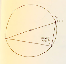
The number of right angles which can be drawn in a circle is infinite. The rule always works. That understanding is part of why geometry is seen as mystical or sacred.

This 'squaring the circle' diagram is from
Robert Lawlor's Sacred Geometry*. (page 77, diagram 7.5)
It uses a geometry similar geometry to Biddle's diagram G: a diameter and an angle. Here the diameters are evenly spaced and the same angle  is used at every point on the circumference. But the angle is not 90*. It is not a 'square angle'.
This is decorative, not structural.
The shapes do not close. The line continues for 5 rotations. It does not create a square, but seeks to define the perimeter of a circle with straight lines. 
,
I am often told that I work with Sacred Geometry, that the geometric patterns I recover are theoretical, mystical, and sacred. I agree they are geometry. No, they are not sacred. They are practical. They are geometry used in construction.


Here is how Biddle's diagram comes about: 


Begin with  a point  - A


Choose a radius - A-B,  and draw a circle. Using the daisy wheel find the diameter - B- A- C, dotted and dashed line.


Pick a point on the circumference of the circle - D.

Here I have chosen 3 different D's  at random.

Connect B-D and D-C.


Each diagram will have a 90* (right) angle at the intersection of  B-D-C.


Wherever the D is placed. the angle will be 90*.


Biddle's Diagram G begins with my line B-D.
It describes how to find my 90* angle of B-D-C. (his a-b-c) The answer is to find the diameter of a circle (a-d-c) that intersects a. That will give c. That will give the 90* the carpenter needs.


By Hound and Eye* has a very similar diagram for drawing a right angle .
The book is a  guide to furniture design, full of practical geometry. Each geometric problem is described step by step; practice work sheets are included.
This pattern is the beginning of a handmade try square. 


*Owen Biddle's The Young Carpenter's Assistant, 1805, Philadelphia. Dover Publishing  reprint,  See my Bibliography for more information.

*Robert Lawlor, Sacred Geometry, Philosophy and Practice, 1982, Thames and Hudson, London.

*Geo.R. Walker & Jim Tolpin, By Hound and Eye, A Plain & Easy Guide to Designing Furniture with No Further Trouble, 2013,  Lost Art Press, Kentucky The diagram shown above is from page 57.


This pattern is 4 overlapping hexagons.
My granddaughter, who is 7, watched me add the images to this post.
She wanted us to 'square the circle'. I did, using right angles where the diameters met the circumference. That produced these overlapping 6 hexagons, not squares.


She watched closely and observed that accurate work was not easy: my lines did not always cross exactly in the center of the circle. When we finished she asked me to erase all the diameters. This is the result. Maybe she will show me later what she added to the copy I printed for her. 

Saturday, July 18, 2020

Ruler & Compass, by Andrew Sutton

An excellent introduction to the "basic principles of geometric construction"!

A book I can easily recommend to a beginning geometer or an experienced one.


Ruler & Compass, Practical Geometric Constructions, Andrew Sutton, Bloomsbury USA, NY; U.S. edition, 2009.

It's part of The Wooden Books Series. The fly leaf says "An Introduction to Geometry without Measurements".
Andrew Sutton is a high school math teacher in the UK.

His illustration at the bottom of his dedication page:


This is a small book, 6" x7"  with 30 chapters, 58 pages. It includes sources, history, and many illustrations. It is dense, full of great details, but not intimidating.
He begins with an Introduction, Fundamentals, Perpendiculars, and Parallels.


These are his diagrams for his chapter (2 pages long)  "Squares & Rhombuses from lines and circles".

I had fun comparing Constructions 34, 35, and 36 to Asher Benjamin and Owen Biddle's instructions. Both 34 and 35 constructions seem easier and faster than theirs.


These constructions are also variations of ones  I've used.


At the end are an Appendix Polygon on Grid Construction and an appendix on Polygon Combinations.
This construction from page 56 is repeated and refined in 5 different ways.


The book refers to construction only as it is found in ancient Egypt and India. He does include diagrams by Serlio and Vignola, but seems to reference them through others, not from Serlio's and Vignola's own writings and diagrams.


I would like to hear his thoughts about Practical Geometry as it applies to construction.


Sunday, July 12, 2020

The Miller's Toll, Bennington, VT - its construction


The Miller's Toll is a restaurant in Bennington, Vermont. 

This post is about the building's construction.


The current  owners knew they had an old building when they began renovation in 2017. 
I asked to explore the place while its frame was visible. They agreed, with pleasure.
I wrote about its history on my blog, 'Passing By'*.


The main house, now surrounded by first floor wings and a second floor jut-out, is a post and beam frame with plank walls.
This framing system is not uncommon locally. Occasionally plank walls were used in western NY and Ohio; indicating that framers who had learned their trade here built there. 

First:  what I saw and some history.


This is part of the plate for the roof of the back wing. It was now part of the 2nd floor wall frame.
This back wing may be the original house - a small raised cape (half walls on the 2nd floor - modified Anglo-Dutch frame) typical for this part of Vermont.
The main house may have been added as the owners and the town grew.


The building is on every map we have of the town. It is a black spot on the first - the 1835 Hinsdill map. It is also a spot without a name on the 1856 Rice and Howard map.


This is part of the 1867 Beers Atlas map.The house is in the middle with the owner's name (illegible) jutting up. M C Morgan's house - now the Safford Inn - is just to the right, across the Walloomsac River.
The Safford family were early settlers of Bennington. They built the house and ran the corn and saw mills across the road. The mills are depicted on both maps. M.C. Morgan inherited the house.


Here is a small part of the 1877 Bird's Eye View Map of Bennington. and the same map updated in 1887.


In the middle, beside the Walloomsac River,  above and left  of the bridge, is the house.
It is a 2 story house with a back wing and a porch on 2 sides. There are 3 windows on the second floor in the front and a chimney in the middle.


It appears that the front porch was enclosed by 1887, or perhaps the delineator was more skillful.


The hole in the roof for the chimney is now patched. It is right where the map placed it.

It's the house which was here in 1877.

The front wing had one chimney and no fireplaces. Cast iron stoves were manufactured locally as early as 1820. This house probably had one. 


 A view inside the 2nd floor of the front wing, probably built   before 1830. 

The 3 windows seen on the map are there.
The roof has the same pitch with the gable facing the street.
The bunch of wood in the  photograph in the middle of the floor - where the surface changes -  covers the hole where the chimney was.

The gable of the house faces the street, an early step in the evolution from late Georgian to Greek Revival vernacular architecture. However, I could see no framing showing a stair had been located in a hall on one side of the front wing, also a hallmark of Greek Revival.
A simple stair was set between the back wing and the new one.  The pale sliced rectangle, lower left, is the first step for that stair. Its frame was not visible, its moldings cobbled together - I couldn't date it.


The ridge beam, running down the middle of the picture, has 5 sides. These ridge beams were standard in Bennington houses from c. 1770 to the Civil War. Wide boards with wane were used for roof sheathing.


The ceiling joists ran parallel with the  ridge, set into the beam. This is also common locally. In the photograph a later ceiling frame is barely visible.
I saw no scribe marks; this is a square rule frame.


The post and beam frame, painted here in the photo, is typical of New England timber frame construction found in Bennington from 1765 into the 1860's.


The walls have no studs. Instead planks sit side by side.  Bennington had lots of wood. Water powered saws quickly cut that wood into many wide panels. The intermediate studs we had earlier used in the post and beam frame gave way to plank walls.

The availability of wide boards was due to advances in saw mill technology. The contemporary sash saw could cut several boards at once; earlier saw cut only one board at a time. The proliferation of these boards may be part of why we began to add wide corner boards, wide frieze boards under the eaves, to outline pediments in gables -  to cover our simple, traditional house shapes in Greek Revival decor.  


Those planks were cut at Safford's saw mill just across the Walloomsac River.
The sash saw blade went up and down. It left the marks on the boards which are still visible today - the left side in the photograph.

On the right side are the light and dark marks left from where lath was nailed on for plaster. The uneven lines mean that the lath was 'split'  - made from  boards. Later lath is all one width cut instead of being split. 


In1896 the Sanborn Insurance map labels the house a Cigar Manufactory" . Here is the owner's advertisement in the 1896 town directory.
Later it became a market, then a restaurant - The Vermont Steak House, Peppermills, and now The Miller's Toll.


When I posted a link on a local history page a lively discussion took place on cigar manufacturing and small town employment in the early 1900's. The outer layer of the cigars came from Connecticut River Valley tobacco fields, the delivery made possible by the railroad to N. Adams that used the Hoosick Tunnel, an engineering feat for its era.
Young women with nimble fingers were employed to roll the cigars. Immigrants were usually hired as speaking English was not required.


*I wrote about it in my local blog:
https://passingbyjgr.blogspot.com/2017/01/the-vermont-steak-house-was-cigar.html


Monday, June 29, 2020

Practical Geometry Lesson 5, Addendum


Why I left out diagram K from Owen Biddle's Plate 1 in his Young Carpenter's Assistant.

Lesson 5 was written for a student today who wants to draw rectangles using practical geometry.
Biddle was writing for the apprentices he worked with in 1805. They needed to know the practical application of geometry for the buildings they worked on - including the curved parts.

This addendum is like one of those long footnotes in an historic report -  a part of the story that's not quite germane to the subject, but ought to be included.


Biddle  identifies each diagram on Plate 1with a letter. There is no diagram for D. However, in his text, between C and E he discusses the mathematical instruments a carpenter should obtain. Perhaps this is D.  I quote him:

- scales of equal parts on the thin ivory or box rule
- a bow pen or compass
- a small piece of gum elastic for rubbing out black lead lines
- a stick of Indian ink
- 2 camel's hair pencils, one large, one small
- a black lead pencil


There is also no J. And there is no text in its place as exists for D. 


Here is K.  

Biddle writes: "Three points (not in a right line) or a small part of a circle being given to find a center which will describe a circle to pass through the points or complete the circle."


                                                     Start with a curve a-b .
                                 The curve in Biddle's drawing above is a-b-c.                       


 The curve divided in half:  Swing 2 arcs that are the same length  above above and below the curve: a-c and b-d. Mark where they cross, at f above and below the curve,


Connect  f and f with a line - here dashed. Mark where the line crosses the arc a-b -  I've labeled it g.
This line divides the arc in half. 
If 2 lines were given - here: a-g and g-b , this step would not be necessary. Biddle's diagram  labels his lines a-b and b-c.


Now, the instructions become complex.
Draw it step at a time. And consider that this is only Plate 1 of Biddle's pattern book. He included 43 more Plates for the carpenter's assistant.  

Divide the lines a-g and g-b in half.
This is shown in Biddle's E  and F diagrams. Check Lesson 5. 

Extend the lines which divide  a-g and g-b in half so they intersect at k,
K is the center of the circle which passes the points or completes the circle.

Refer to Biddle's drawing K above for the complete solution, all neatly explained in only one diagram.  


Clearly Biddle thought this information  was essential knowledge for  every carpenter. His next Plates illustrate why. The construction his 'young carpenter's assistant' would be working on involved determining and laying out many curved lines for vaults, arches, windows, stairs and railings.


Plate 2 discusses ellipses: how to draw them using geometry or a trammel, how to find the center and axes of one already drawn.   


Plate 3 is concerned with octagons, arches, groins. the use of trammels, how to divide a line into parts.

I am quite fond of Figure 1, describing " an Octagon within a square." . Simple, quick, even obvious - if you know geometry.

I have seen  painstaking explanations of  how to lay out an octagonal using algebra: quite painful.


Plate 6 reviews raking cornices and "the sweep of a cornice which will bend around a circular wall and stand on a spring."


Plate 31 lays out "the section and elevation of a circular or geometrical stairs". Biddle includes in figure C  "the manner of drawing a bracket for the ends of the circular steps..." and the careful, detailed instructions.


Plates 32-35 - not included here - explain how to layout the newel, the falling moldings, the hand rail for such a stair.


Biddle's Young Carpenter's Assistant, Owen, Biddle, 1805, originally published by Benjamin Johnson, Philadelphia, and Roland and Loudon, New York. Reprint by Dover Publications, Inc. 2006. If you want this book, you can easily order it from them directly. It has an excellent 15 page introduction with bibliography by Bryan Clark Green.


The posts in this series  Lessons 1-7  are :

 https://www.jgrarchitect.com/2020/04/lessons.html

 https://www.jgrarchitect.com/2020/04/practical-geometry-lessons-2.html

 https://www.jgrarchitect.com/2020/04/practical-geometry-lesson-3.html

 https://www.jgrarchitect.com/2020/04/practical-geometry-lesson-4.html

https://www.jgrarchitect.com/2020/04/practical-geometry-lesson-4b-old-first.html

https://www.jgrarchitect.com/2020/06/practical-geometry-lessons-lesson-5.html

https://www.jgrarchitect.com/2020/06/practical-geometry-lesson-5-addendum.html

https://www.jgrarchitect.com/2020/08/lesson-6-rule-of-thirds-part-1_21.html

https://www.jgrarchitect.com/2020/08/lesson-6-rule-of-thirds-part-2-serlio.html
 
https://www.jgrarchitect.com/2020/09/lesson-7-how-to-layout-frame-with-lines.html

Tuesday, June 16, 2020

Practical Geometry Lessons, Lesson 5: Rectangles


Today these skills are not required knowledge for builders. We have steel carpenter squares that have true 90* corners, as well as levels and  lasers. 


The carpenter squares shown here are some of the earliest made in the States. They were made in Shaftsbury and N. Bennington, VT, 1825-60. Some are on display at the Bennington Museum; all are available for study.

The 1503 woodcut at the end of this post includes a square being used for a layout. That square might not have matched the square of another builder.

Practical geometry taught how to 'prove' that an angle was 'true'. Carpenters today still make their work 'true'.  


This "Geometric Problem'  and its solution was particularly important when carpenter squares were not necessarily true: the square corner was not always accurate, not dependably 90*.

This is the end of Lesson 5.
The carpenter's assistant who masters these problems is now ready to assist in layout and framing. Maybe he (no recorded 'shes' that I know of) will go on to learn design. 


For more ways to draw a square  see Drawing a Square, Parts 1 and 2.
Part 1: https://www.jgrarchitect.com/2019/12/practical-geometry-drawing-square-with.html
Part 2: https://www.jgrarchitect.com/2020/01/practical-geometry-drawing-square-with.html


After-thoughts and questions:

How did carpenters carry a 10' rod?  Did the rod fold, or come in pieces that could be connected with pegs,  perhaps leather sleeves?
I have seen one in a medieval print, part of which is shown here.

The builder on the left uses a square for layout. Below him is an axe, a saw, and a level with a triangular hole and a plumb bob.
The builder in the center holds a 10' rod.   The landscape to his right is the site where he will layout a building, or perhaps land.
 A 'rod' when used in land surveying is 16.5 feet long. It is also called a 'perch' or 'pole'. How did they carry that awkward length? 'Links' and 'chains' are also used in surveying, so perhaps a rod could be a length of chain.

 Woodcut by Gregor Riesch, Margarita Philosophical, published in Baden,1503.


The posts in this series  Lessons 1-7  are :

 https://www.jgrarchitect.com/2020/04/lessons.html

 https://www.jgrarchitect.com/2020/04/practical-geometry-lessons-2.html

 https://www.jgrarchitect.com/2020/04/practical-geometry-lesson-3.html

 https://www.jgrarchitect.com/2020/04/practical-geometry-lesson-4.html

https://www.jgrarchitect.com/2020/04/practical-geometry-lesson-4b-old-first.html

https://www.jgrarchitect.com/2020/06/practical-geometry-lessons-lesson-5.html

https://www.jgrarchitect.com/2020/06/practical-geometry-lesson-5-addendum.html

https://www.jgrarchitect.com/2020/08/lesson-6-rule-of-thirds-part-1_21.html

https://www.jgrarchitect.com/2020/08/lesson-6-rule-of-thirds-part-2-serlio.html
 
https://www.jgrarchitect.com/2020/09/lesson-7-how-to-layout-frame-with-lines.html