Showing posts with label Henry Glassie. Show all posts

Tuesday, October 3, 2023

Teaching Practical Geometry


 Several educators, curious about Practical Geometry, have asked me how I would share this geometry in the classroom. This post is an introduction to how I would begin.

In September, 2023, I presented 3  workshops at IPTW, the International Preservation Trades Workshops.* The last day was open to the public. About 10 people, aged 10-70+, came to learn about Practical Geometry. Some had never held a compass.  

Here is what we did:

We drew circles with compasses. Then we divided the circumferences into 6 equal parts and connected the points to make rectangles and squares. We used no numbers. 


We  explored the  design and layout tools a carpenter would have had before the Industrial Revolution: the compass, a line and a scribe. We talked about how those tools were used and are still used. We compared cubits (the length from your elbow to your longest finger).  We set carpenter's dividers for a day's work by the radius or the diameter of a daisy wheel. One of the participants taught the others how to snap a chalk line.

I brought my daisy wheel with me. It was scribed into a 9 ft tall board which was once sheathing on Vermont barn, c.1780. The barn was deconstructed about 10 years ago. The deconstruction contractor gave me the board.


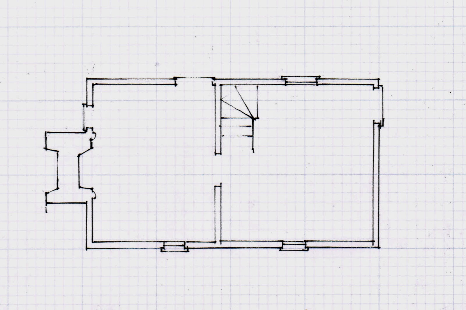
I showed them the floor plan of one of the early Virginia folk houses recorded by Henry Glassie,** which used the geometry we had drawn. 


I shared a few pictures including this house whose plan we had just laid out.  


That image introduced the class to the chimney wing. Its plan would have used the 3/4/5 rectangle to make sure the wing was parallel to the house so that all the roof framing could be cut the same length.  


I showed the group a Menagery, a retreat intended for an English gentleman's estate, designed by James Gibb's ***, c. 1720.  


 The wings are laid out in the same way, using the 3/4/5 rectangle. Here it is because the rough laid stone on the exterior would have made an accurate layout and construction difficult.


Then the class learned about the 'star', the Lines, in the center of the Menagery. Those are also the lines on our cellphones which help us edit images, known by artists as the Rule of Thirds.  

Here is the geometry: the diagonal of the square and the Lines from the ends of one side (the corners) to the middle of the opposite side. The  pattern is turned 4 times.


Where the lines cross are points. 2 points connected are a line. That line is always straight.

Here, the points divide the large square into 9 small squares - the diagram used on cellphones - or 3 equal rectangles.

There are also 4 squares within the large square. If their diagonals are drawn, the large square can be divided into 16 small squares or 4 equal rectangles.


The Lines on the elevation for this brick house tell the mason where the sides of the door and window openings are. On the plan the Lines show the fireplace edges and the placement of the interior walls. 

The drawing is Plate 56 in Owen Biddle's pattern book, The  Young Carpenter’s Assistant,  published in 1805, by Benjamin Johnson, Philadelphia.


 I ended with these Lines in Sebastiano Serlio's Book I, c. 1540. It explains where to place a door in a castle wall. He ends Book I: On Geometry, " However, honest reader, although the things resulting from the various intersections of lines is infinite, to avoid being long-winded I shall come to an end."


This was more than enough for one 75 minute session. 

Several shorter lessons would have been easier for everyone. There was very little time for questions, more examples, or in-depth understanding.  


For more information: In 2020,  I wrote 7 posts entitled 'Lessons' for students of all ages. https://www.jgrarchitect.com/2020/04/lessons.html .

*The 25th International Preservation Workshops were held this year in Frederick, MD, at the Hargett Farm which will become the Historic Preservation Trade Center for the National Park Service.          See the Preservation Trades Network website, ptn.org, for more information.

** Henry Glassie,. Folk Housing in Middle Virginia, U of Tennessee Press: Knoxville, 1979

*** James Gibbs,  Book on Architecture, London, 1728, Dover reprint

**** Sebastiano Serlio . On Architecture, Lyon, France 1530, translated in1611,  on-line and translated by Vaughan Hart and Peter Hicks, 1996, Yale University Press, New Haven

To read more about this diagram see https://www.jgrarchitect.com/2022/10/serlios-lines.html 


Tuesday, January 10, 2023

Geometry in Construction = Practical Geometry


Geometry in construction = practical geometry.

Does that seem strange, a philosophical stretch?  As recently as the 1930's it was widely understood, commonplace.  Since the 1950's, geometry has been taught as precise, logical, beautiful, magical, amazing.  But practical? Barely. Today the idea is usually met with skepticism.

However, you who read my blog know this is what I study: what those builders know about geometry and how did they use it? 


Euclid's geometry starts with a Point which has no dimensions.  Two points make a Line - 1 dimension3 make a Plane - 2 dimensions.


4 points make an object  - 3 dimensions.  


How can this geometry be practical? 

A Line laid out between 2 points will always be straight. 

A Line drawn by hand might curve; a Line marked by snapping a length of twine cannot curve. This is the beginning: it will be true.  If the geometry is not accurate it will not be practical.

The Line A-B can become a radius. The radius can draw a circle. 

Whether the circle is drawn with a compass set to the length of the radius. or by hand with a length of twine, it will close if the the work is accurate. If the circle does not close upon itself it is not true.        At every step of the layout if the geometry doesn't hold, the designer will know to stop and correct the drawing.


The radius of the circle always divides the circumference of the circle into 6 parts. If the points on the circle, marked by swinging the arc of the radius, are not spaced accurately they will not end exactly where they began. They will not be true. The work cannot proceed. These 6 points on this daisy wheel are not quite accurate.  Note that the daisy petals' shapes are not identical; the points are not equidistant. If I measured the diameters, petal to petal, they would not match. I was not careful enough.        


 The 6 points, joined with lines, can be used in construction.


The rectangles that come from the 6 points can be proved by their diagonals. If they match, the rectangle will have 90* corners and be true. If the diagonals do not match the shape is not a  rectangle. 


A building needs to be stable, whatever materials it is made from, whatever form it takes. For simple vernacular housing the circle was the practical geometry needed to erect a stable, sturdy dwelling.  


The layout tools available to the builder of the Lesser Dabney House* in rural Virginia, c. 1740, were twine, some pegs, a straight edge, some chalk or soot so the twine could mark a line, perhaps a scribe, a compass.

The builder could have laid out this house with the first 4. A peg could have served as a scribe to mark a point. Twine with a loose knot around a peg turns as a compass does.


Here is the floor plan as it was recorded by Henry Glassie, c. 1973: 3 rooms with 2 chimneys and a stair to the attic.  3 windows, 4 doors. The door to the left may have gone into another shed.


The builder stood where he wanted the main wall of the house to be. He pegged the width he chose with twine A-B. That length became his radius. He drew his arcs to find the center of his circle C. Then he drew his circle.  And found it true. The circle's radius steps off 6 times around its circumference. The arc create the 'daisy wheel'.


A-B in the diagram above became 1-2,  the width of the house. The arcs 1-3 and 2-6 of that width crossed at the center of the circle with its 6 points: 1,2,3,4,5,6

The Lines 1-5 and 2-4 laid out the side walls; 6-3 locate the back wall. Diagonals across the rectangular floor plan proved the layout to be true.


The main block is about 20'x17'. The 2 doors  welcomed cooling through breezes in the summer. The wall room on the right may been a later addition to create a parlor, more private and warmer in winter.

Then the builder added the shed. He made his twine the length of the house, folds it in half and then in half again. He then knew what was 1/4 the length of the house (x). He laid out that length (x) 3 times to get the depth of his shed. He stretched his twine diagonally from one corner to the other. If the twine measured 5(x) his shed walls were a 3/4/5 rectangle; the corners 90*, and  true to the main house. The shed roof framed cleanly against the house and was weather tight.

The circle and the 3/4/5 triangle - Practical Geometry -  were the only measuring systems necessary to construct this house.


*The Lesser Dabney House, Fig. 45, Type 3, p, 105; the photograph: p.104. 

Henry Glassie, Folk Housing in Middle Virginia, U Tennessee Press, 1975; plans, drawings and photographs by Henry Glassie.

Henry Glassie recorded floor plans and what history he could find, He photographed. He did not make measured drawings like those in HABS  now in the Library of Congress and available on its website.


Tuesday, November 29, 2022

Virginia Folk Housing, Part 2 of an update


The Moore House* photographed by Henry Glassie, built before 1750.


This house has 2 rooms up and down, 2 fire places, 2 chimneys, and a shed on each end. The main block  is double the size of the house I wrote about in Part1: https://www.jgrarchitect.com/2022/11/virginia-folk-housing-update.html

The geometry begins as it did in Part 1, using the width as the circle's  radius.   


Here is the floor plan: 2 rooms with fireplaces, and sheds on both ends.


The daisy wheel progression begins with a length A-B which becomes the radius of a circle here lettered C-A.


The daisy wheel for this house begins with the left wall of the main house.


That wall's width  is the radius, 1-6. A is the center of the circle. The daisy wheel lays out the other 4 points, 2, 3, 4, 5.  

 Lines 1-3 and  6-4 are the sides of the house. 2-5, the diameter of the circle, lays out the interior wall.


Lines 1-5 and 2-4 can extend forever. Where is the right end wall of the house located? Where is C

It's at the end of the circle, but that's only a point, not a line. 2 points are necessary to draw a line to mark the right end of his foundation and the floor of the house.

If the carpenter extends his arcs he can quickly find the missing points. 

Extend the arc centered at 3 (2-A-4) to B.  The arc centered at 4 (5-A-3) crosses the earlier arc at B.   He has 2 points: A and B, And can draw line A-B

Now C is fixed at the intersection of A-B. C is the center of a new arc, (7-A-8). The extended arc from 5 (6-A) crosses at 7. The arc 2 (1-A) crosses at 8. 7-C-8 locates the right wall.

C also locates the center of the fireplace and the chimney. 

The daisy wheel is often dismissed as a design tool. It is flexible, quickly drawn, and accurate. 

The geometry comes from the first length - the width chosen by the owner and builder for this house. That width, and the house, could be bigger or smaller to suit the owner's needs and budget, as well as to the lumber available for joists and rafters. 

Once the carpenter decides on a width he uses one compass setting, one radius, for the whole layout. Every point is checked. As the lines are marked, the diagonals can prove the layout to be  true.

If he drew a layout at a smaller scale, he could easily step off to full-sized construction dimensions with his compass. He could also draw the layout on the ground, stake the points and mark the wall locations with twine just as framers and masons do today. 

Consider how the plan would be laid out if the circle is not used. Use a 10' pole - a common tool of the time.  Each corner would need to be figured independently;  every dimension stepped off separately, and with what accuracy? 

The daisy wheel locates all angles and lengths quickly. It has built-in checks from the beginning and as the layout progresses: if the circle doesn't close, the 6 points will be uneven, the arcs won't cross, the diagonals will not match. The layout will not be accurate.


 Both wings are 3/4/5 rectangles. See the left shed. The floor plans of wings were usually 3/4/5 rectangles so that they would sit square to the existing house. All the joists would then be the same length; as would be the rafters.  


My earlier complex geometry 'works'; the lines are there. But they don't give the basic information the builder needs: the dimensions of the foundation, the floor plan, the size of the house.


*The Moore House, Fig. 31, Type 5, p, 77; the photograph: p.76. 

Henry Glassie, Folk Housing in Middle Virginia, U Tennessee Press, 1975; plans, drawings and photographs by Henry Glassie.


Monday, November 14, 2022

Virginia Folk Housing, Part 1, an update

The house recorded by Henry Glassie in Folk Housing in Middle Virginia * were basic shelter for people with few resources. They may have been the first house for someone homesteading, built by a sharecropper or by someone enslaved.   

This is Fig. 35, The Parrish House, a "small mid-eighteenth-century house of sawed logs", p. 84 in Glassie's book.*


The geometric diagrams I drew in May 2014,** were accurate but much too complex for these houses. More importantly they didn't begin as a carpenter would: with the size of the foundation and the floor plan.


 A carpenter's first question is, " Why?" Then he asks, "How big? How long? How wide?" 

The red line across the bottom of the floor plan is 'how long', about 21 ft. That distance can be the beginning of the layout, the first Line that determines all the others.


That Line can be the radius for a circle:


The arcs of the Line A-B cross at C. That's the center of the circle for the layout of this house.

In the diagrams below: 1) B-C is the radius of the circle. 2) Beginning with B on the circumference  the arcs of the daisy wheel are added. The 6 even spaced points around the circle A, B, D, E, F, G  are located.


Connect the Lines. A-F and B-E are perpendicular to A-B. G-D is the diameter. They mark the width and length of the rectangle for the house plan.  If there is a question about accuracy, diagonals can be used to true the shape.


Here is the plan within its circle, the circle that begins with the carpenter's choice of width, his 'module'.


The masonry block for the 2 chimneys is square, centered, and 1/3 of the width the house. Glassie's photograph shows a shed sheltering that fireplace.


Part 2: https://www.jgrarchitect.com/2022/11/virginia-folk-housing-update-part-2.html

Another introduction to the geometry: https://www.jgrarchitect.com/2023/01/geometry-in-construction-practical.html


*Henry Glassie, Folk Housing in Middle Virginia, U Tennessee Press, 1975. The book includes more information, drawings, and a photograph of the house. It no longer exists.

** The original post is here:  https://www.jgrarchitect.com/2014/04/18th-c-virginian-folk-houses.html. Its companion, here: https://www.jgrarchitect.com/2014/05/18th-c-virginian-folk-houses-part-2.html

I considered deleting the 2 posts, but their existence brought a comment and question which prompted this update.

Also:

As I read them I realize how much I have learned about geometry since 2014. I saw it and tried to explain it, just as Henry Glassie did in his Rules, Chapter IV, The Architectural Competence.

When I began to study Practical Geometry there were no books, no one for discussions or critiques. I was teaching myself, reading early pattern books line by line. Laurie Smith was the only person I knew who saw geometry as I did, and he was in the UK. Later that year he came to the States; I took a workshop with him. I was able to work with him until his death last year.  

I don't want this information to be lost again. I want others to find it, question it, reject and/or improve upon my analysis, their own analysis, expand our understanding.


Monday, June 2, 2014

Cabin, Tuckahoe Plantation Goochland County, Virginia

I came to Tuckahoe Plantation to look at the cabins. Drawings for them are in the HABS archives. They are the size and layout of the houses whose floor plans Henry Glassie recorded and whose geometry I have written about.
 Dr. Glassie's book,  Folk Housing in Middle Virginia, includes photographs of poorly maintained houses, most beyond repair.

I wanted to see what they might have looked like when they were built and how tall they were. Yes, the HABS elevations show how tall they are. However, for me reading a drawing is a beginning, one  part of
understanding. I need to see the building.


It is very simple. in appearance and geometry, and not only because of its shape and lack of anything beyond the essentials.


It is just squares: 2 across the front, 2/3 of a square for the sides, 2 for the floor plan.


The chimneys are centered on the square.


The doors and windows are centered on the plan and on the center of the square for the front elevation.


The  front and side elevations are two thirds of the square.

 The roof pitch is 12/12 - the diagonal of the square - and begins at the 2/3 line of the lower square.


This way of dividing a square and using the diagonals to determine dimensions is called the Rule of Thirds.
To learn how it is drawn please see my blog post:
http://www.jgrarchitect.com/2016/10/practical-geometry-drawing-diagrams.html


The book, The Chesapeake House, reports that the plastered interior walls of the house are original as is the door between the two rooms. This 'cabin' then perhaps was built for the use of an overseer, or craftsman.

As you can see from my photograph, the little house sits on a green lawn with a dirt path, surrounded by towering leafy green trees. Clean white paint, variegated wood shakes on the roof, a neat brick chimney - all in excellent condition - may give too cheerful an interpretation of conditions in 1750, but I am glad it is being preserved.
Studying the adjoining kitchen, office and storehouses, walking down the path, then around behind the cabin across the lawn to the main house, gave me enough understanding so that as I traveled back roads to Madison's Montpelier I easily spotted similar cabins, now out-buildings on farms or wings to later homes. At Montpelier, where timber framed and log cabins are being rebuilt, I was also able to better read what was there. My visit to Tuckahoe was excellent.

The Chesapeake House, architectural investigation by Colonial Williamsburg, edited by Cary Carson and Carl Lounsbury, The colonial Williamsburg Foundation and the UNC Press, Chapel Hill, 2013.


My previous post about the main house at Tuckahoe Plantation is here: http://www.jgrarchitect.com/2014/05/tuchahoe-planatation-richmond-virginia.html


Thursday, May 1, 2014

18th C. Virginian Folk Houses, Part 2

Please see 18th c. Virginian Folk Houses, Part 1, where I describe why I am looking at Henry Glassie's book, Folk Housing in Middle Virginia, 1975, U. of Tennessee.

NB: These 2 posts have been updated with new posts as of November, 2022.

I am using Dr. Glassie's drawings. I am thankful for the chance to look at the geometry to the houses, many of which no longer exist. But I can't verify when I have a question. For example, "Is the window right there or maybe a few inches over? That would fit the symmetry.... " "The drawing isn't quite square. Is that caused by
the printing or was it real?"

I would really like to have been there as the houses were built. Then I would know. I need Dr. Who's Tardis.

So, between now and the loan of the Tardis, I have decided to make some assumptions for this next house.

It is the Lesser Dabney house, figure 45, Type 3, House V.Dr. Glassie's book includes a photograph and several other drawings of the house. It was probably built after 1770.


The original house included the chimney, but not the shed on the right.


 I have outlined the house in red.
There are 2 overlapping squares -'a-a-a-a' and 'b-b-b-b',  or 3 equal rectangles made up of 2 small squares each - 'a-b-b-a'. or half of the large square. This is where I am taking liberties - Dr. Glassie's proportions is not quite as true as I have shown them. The parts do not line up as neatly if I scale on his drawing. But when I make them neat - a couple inches either way, they fit in a simple pattern.

I have drawn the diagonals that determine placements with a green dashed line. The determining lines are a green dash and dot line. At the end of the ones I think are where they belong I have added an arrow. Where it doesn't quite work - but so close! almost! - I have added a question mark:'?'. The shed's dimensions are determined by the width, divided in 8 parts, and the length, the extension made from 3 of those parts. This results in 2 3-4-5 triangles and assures a square fit of the wing to the house.


Here is the roof frame of the Lesser Dabney house,
Figure 69, The Loft, a section through the frame of house V.
Dr. Glassie included the interior wall finish (I think). I have left out that line.


Thinking about how the roof would have been framed to sit on the walls below, I extended the line of the posts as high as the peak. Then I crossed the diagonals to make the square, and crossed the collar ties at their juncture with the rafters. The center-line of the square crosses at the top of the knee walls. the diagonals of the half square cross the diagonals of the full square at the ceiling joists.
I am sure there were other considerations: reinforcing the eaves where they kick out, and tying together the rafters at a point where they will adequately hold the frame, but leave enough head room to make the attic useful.


Both of these two houses are they were printed in Glassie's book, Folk Housing in Middle Virginia. I didn't adapt anything. The geometry was obvious and easy.

This is Figure 39, The Central Hall I House, West of the Blue Ridge. A.
It is in the Valley of Virginia. The right side, through the entry hall, is built with logs. The left side added later.
The pattern of the original house is familiar: the square - red solid lines - and its half squares - red dashed lines - with the intersections of the diagonals marking window openings, chimney width, placement of the wall between kitchen and entry hall, and the  1/4 width added to the square to give the entry hall enough space for a turning stair- green dash and dot lines.

Then the left wing was added. Its dimensions are the 3-4-5 triangle - black dashed lines - with the existing wall designated as '4'. Its center-line locates the windows - green dash and dot lines again.
The windows on the front wall are not quite equi-distant from the corners, but close enough to read as balanced.


Finally,  Figure 39, The Central Hall I House, West of the Blue Ridge, B. A house in Falmouth, Pendleton County, Kentucky.

Both rooms are square - red lines, their windows, doors, and fireplaces are on axis - green dash and dotted lines. The circle around the square - red dashed line - determines the width of the hall, the relationship between the 2 rooms. It could also be found by turning the square 45*. Those intersections also place the doors into the hall and the fireplace and closet in the left hand room - green dashed lines for the turned square.
This  house, if its chimney in the right hand room for a cast iron stove was built with the house, may date to the 1830's.


Saturday, April 26, 2014

18th c. Virginian folk houses, Part 1

Henry Glassie in his book,  Folk Housing in Middle Virginia, U. of Tennessee, 1975, discussed the 18th c. folk (now usually called vernacular) houses of Louisa and Goochland Counties, Virginia. He recognized that their plans were based on variations of a square and analyzed the ratios he saw.
His illustrations include photographs and measured floor plans.

Because I have only examined buildings in one part of the country, the Northeast, I wanted to look carefully at the vernacular houses he recorded.
From Henry Glassie's drawings could I determine whether or not the house-wrights use geometry? If so what kind? Did settlers in Virginia bring or develop different framing geometries from those in the north?

 Many of these houses had back-to-back fireplaces, one in the main house, one in the adjoining shed. A chimney and fireplace in the 1700's was essential; its cooking fire never went out; it was the source of heat and light. So I include it in my analysis. Here are 3 similar geometries. I have redrawn the plans on graph paper.


Please click the diagrams to enlarge them.

This is The Parrish House, Figure 35,Type 3, in Dr. Glassie's book, mid- 18th century, built of sawn logs dovetailed at the corners.

Its geometry, shown below, begins with  a square, drawn with two solid lines and its diagonals in red. The location of the left window. and the doors are determined by the center. The upper window is located by the half square and its diagonal - a dash-dot red line. The window and door locations are  drawn with a dash-dot green line. 
The rest of the room, including the chimney, comes from half  of the square extended on the right side, dashed red line. That rectangle, divided in half , red dash-dot lines,  and its diagonals, green dash-dot lines, position the right wall and the chimney mass.  I have added green arrows to show those intersections. 
It feels crowded on the drawing, but on site there would have been plenty of space and it is the same geometry each time, just on a smaller scale.

I think the partition wall was a later addition, blocking the stair as it does.  

When I first drew this I thought the size was derived from the Golden Section. I kept looking for a solution based on just a square because the house is static, solid, not fluid. The Golden Section grows; it is dynamic.


This house Dr. Glassie called Unique House. It is House G, Fig. 29 in the book. He notes that it originally had a chimney on both ends.


The red square on the left begins with the chimney. Its right side is the partition wall between the rooms. the right room is a square of the same size. The left outside wall is determined by the square again, just as in the Parrish House above.
If the square starts at the left wall, the right side is at the edge of the stair. See the green square. If the missing chimney is added to the right, the square that would begin on its outer side would also have its left side at the stair. Each side would be the mirror image of the other.
The dot and dash green verticals through the centers of the squares determine the door frame and the center lines of the windows. The right green center-line is canted about a degree, not truly vertical. But the Glassie drawing indicates that the fireplace is also not centered, so I drew it in.  


This is The Moore House, Figure 31, Type 5, House H in Dr. Glassie's book. There is also a front elevation of this house in the book.
The plan shows two main rooms with a shed on each end. A turning stair is located in the back left corner of the larger right hand room.


The main house is composed of 2 squares, drawn in red.  The square to the left includes the chimney. Its green center line locates the center of the windows. The diagonal of half the square crossing one of the 4 small squares within the main one determines the placement of the left wall for the room. See the green dot and dash lines on the left square.
The chimneys on both sides are centered on the squares. But the right chimney is outside the square. Here the smaller square's diagonal and the diagonal of its half rectangle position the chimney base. I've used a green dot and dash line here to mark the intersection as well as the window and door locations for this room.

The sheds on both ends were probably added after the house was built. They are both  laid out as 3-4-5 triangles insuring that they would sit parallel to the existing house. See the dashed and broken black lines on the rooms on either end.

Unlike the buildings in New England and New York, the Virginia houses have only approximate dates and many of them no longer exist.

5/14/2014: I have just returned from driving back roads in Louisa and Goochland Counties, VA, looking at houses that are similar to these recorded by Dr. Glassie. The form is still visible, sometimes as a wing of a larger house, sometimes an out-building on a farm, sometimes in ruins. However, not once did I see a firebox that could have been used outside. This makes me think the houses Dr. Glassie recorded were half of an original house.