Showing posts with label Bennington. Show all posts

Friday, February 21, 2025

William Pain's 'The Practical Builder' and Lavius Fillmore


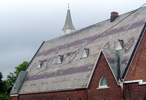
 Here's the Old First Church, Bennington, Vermont.*


In 1803 the church elders invited the Master Builder, Lavius Fillmore, to build a new church in Bennington. He had already built 4 churches in Connecticut. The latest had been included in Asher Benjamin's first pattern book, The Country Builder's Assistant, published in 1797.**                               

Pattern books were architectural guide books for builders. Their images were studied and copied by gentleman scholars and master builders; their instructions studied and followed by apprentices, journey men, and carpenters.

William Pain, in London, had written many pattern books, 8 of which are known to have been available through book sellers and in private libraries in the States. While there is no written record of what pattern books Lavius Fillmore owned or might have seen, I think he must have studied Pain's The Practical Builder, printed in London in 1774.***


Here is the evidence:


This engraving, part of Plate XIV, The Practical Builder, explains the proper design for the 'Frontispiece of the Dorick Order'. Note the fanlight tracery.


 Compare Pain's tracery to that in the fanlight of the Old First Church. 
Fillmore has elaborated upon and refined Pain's design. ****


 The columns  however, do not match the illustration of a Doric frontispiece. They are topped by Ionic volutes. 

In this photograph they look like the ends of rolled up paper. Or maybe balls of white yarn?


This is Pain's 'Frontispiece of the Ionick  Order', part of Plate XVI. 


The volutes match those of the Old First Church.

 On the left side the 'entablature' (the section between the door frame and the roof) also matches that of the church.


Here is Pain's detail of the capital. The right side of the entablature matches the 2 sections, the 'architrave' and 'frieze' of the Old First Church door. 

The volutes on the columns in the church sanctuary also match those on the frontispiece. The columns also have the same architrave, frieze (the top part above the volutes) and the very top part with the dentils - the cornice -  as are shown in the drawing.


Notes:  

*For more about the Old First Church, see the church website: https://oldfirstchurchbenn.org/

** Asher Benjamin's first pattern book is available on line. The original can be read at the Historic Deerfield Library, Deerfield, Massachusetts. We know what books Benjamin studied; he copied their engravings and used them in his own books.

*** William Pain, The Practical Builder, or Workman's General Assistant, I Taylor, London, 1774, Dover Press reprint.

****I have drawn the practical geometry for the fanlight. See: 

https://www.jgrarchitect.com/2021/10/geometry-of-old-first-church-fanlight.html 

I also drew the geometry of the church, 10 years ago. It needs to be rewritten, made simpler and clearer.  

https://www.jgrarchitect.com/2014/11/old-first-church-and-daisy-wheel-part-3.html 


Monday, October 18, 2021

Geometry of the Old First Church Fanlight - an Addendum


The first post about the design of the fanlight is here: https://www.jgrarchitect.com/2012/12/old-first-church-bennington-part-2.html

Considering the 'leaves' of the fanlight,  those 3 curved petals that fan out from the base of the light: how did Lavius Fillmore, the master builder, and his crew, especially Asa Hyde, the joiner, derive the pattern?

The layout that I drew of the leaves in the last post is too complex.


 The church is graceful and direct. 


The derivation in the previous post of the leaf pattern is not direct.
The geometry of the church is straight forward. The use of the circle to layout the framing, the design, would have been clear to other people in construction and to the church's congregation, as well as to anyone in that time who was educated beyond grammar school.


And then there's this diagram in my last post: 

I drew the way the scallops on the curve of the light can overlap simply by rotating the circles one half a petal's width around the circumference, or 15*.

It is also the pattern of the leaves, just at a scale too big for the fanlight.


Drawn smaller, the pattern has 3 overlapping circles at its center, across what would be the sill of the fanlight.  Here the circles come first; the leaves come from the pattern; the fanlight, its size and placement, come from the width of those combined circles.   

However, the pattern in the The Old First Church fanlight was laid out knowing the dimensions for the fanlight. The door and its surround, the placement and size of the door in the main elevation, the width and height of the fanlight were determined by the geometry of the building. They were fixed.

So: given the width and height (about 60"w x 30"h)  how were the leaves' sizes determined? 

The 3 circles across the sill were overlapped. If they were 3 in a row the proportions would be 1/1/1. Then the width could be divided into 3 equal parts. Instead the proportions of the circles are 8/6/8, or 22 equal parts.  Dividing a line into 22 segments with a compass and straight edge is complex.


The center lines  (faint pencil lines here) of one set of the fanlight's scallops meet at the center of the fanlight  These are the scallops that the leaves point to.


The distance between the scallops and the center of the fanlight is the diameter of the circles that will make the leaves. The first circle crosses the pencil lines and marks the center of the next circles.

The red spots are the centers of the circles.


The first 3 inner circles. Where they cross each other and the sill they mark the centers of the next circles.


The 4 outer circles. The ones that continue below the sill are not completely drawn.  Note that even though the center circle begins the design it was not needed here. It was understood implicitly by the joiner laying out the pattern.

Below is the layout of the leaves with all the circles included. 


Sunday, July 12, 2020

The Miller's Toll, Bennington, VT - its construction


The Miller's Toll is a restaurant in Bennington, Vermont. 

This post is about the building's construction.


The current  owners knew they had an old building when they began renovation in 2017. 
I asked to explore the place while its frame was visible. They agreed, with pleasure.
I wrote about its history on my blog, 'Passing By'*.


The main house, now surrounded by first floor wings and a second floor jut-out, is a post and beam frame with plank walls.
This framing system is not uncommon locally. Occasionally plank walls were used in western NY and Ohio; indicating that framers who had learned their trade here built there. 

First:  what I saw and some history.


This is part of the plate for the roof of the back wing. It was now part of the 2nd floor wall frame.
This back wing may be the original house - a small raised cape (half walls on the 2nd floor - modified Anglo-Dutch frame) typical for this part of Vermont.
The main house may have been added as the owners and the town grew.


The building is on every map we have of the town. It is a black spot on the first - the 1835 Hinsdill map. It is also a spot without a name on the 1856 Rice and Howard map.


This is part of the 1867 Beers Atlas map.The house is in the middle with the owner's name (illegible) jutting up. M C Morgan's house - now the Safford Inn - is just to the right, across the Walloomsac River.
The Safford family were early settlers of Bennington. They built the house and ran the corn and saw mills across the road. The mills are depicted on both maps. M.C. Morgan inherited the house.


Here is a small part of the 1877 Bird's Eye View Map of Bennington. and the same map updated in 1887.


In the middle, beside the Walloomsac River,  above and left  of the bridge, is the house.
It is a 2 story house with a back wing and a porch on 2 sides. There are 3 windows on the second floor in the front and a chimney in the middle.


It appears that the front porch was enclosed by 1887, or perhaps the delineator was more skillful.


The hole in the roof for the chimney is now patched. It is right where the map placed it.

It's the house which was here in 1877.

The front wing had one chimney and no fireplaces. Cast iron stoves were manufactured locally as early as 1820. This house probably had one. 


 A view inside the 2nd floor of the front wing, probably built   before 1830. 

The 3 windows seen on the map are there.
The roof has the same pitch with the gable facing the street.
The bunch of wood in the  photograph in the middle of the floor - where the surface changes -  covers the hole where the chimney was.

The gable of the house faces the street, an early step in the evolution from late Georgian to Greek Revival vernacular architecture. However, I could see no framing showing a stair had been located in a hall on one side of the front wing, also a hallmark of Greek Revival.
A simple stair was set between the back wing and the new one.  The pale sliced rectangle, lower left, is the first step for that stair. Its frame was not visible, its moldings cobbled together - I couldn't date it.


The ridge beam, running down the middle of the picture, has 5 sides. These ridge beams were standard in Bennington houses from c. 1770 to the Civil War. Wide boards with wane were used for roof sheathing.


The ceiling joists ran parallel with the  ridge, set into the beam. This is also common locally. In the photograph a later ceiling frame is barely visible.
I saw no scribe marks; this is a square rule frame.


The post and beam frame, painted here in the photo, is typical of New England timber frame construction found in Bennington from 1765 into the 1860's.


The walls have no studs. Instead planks sit side by side.  Bennington had lots of wood. Water powered saws quickly cut that wood into many wide panels. The intermediate studs we had earlier used in the post and beam frame gave way to plank walls.

The availability of wide boards was due to advances in saw mill technology. The contemporary sash saw could cut several boards at once; earlier saw cut only one board at a time. The proliferation of these boards may be part of why we began to add wide corner boards, wide frieze boards under the eaves, to outline pediments in gables -  to cover our simple, traditional house shapes in Greek Revival decor.  


Those planks were cut at Safford's saw mill just across the Walloomsac River.
The sash saw blade went up and down. It left the marks on the boards which are still visible today - the left side in the photograph.

On the right side are the light and dark marks left from where lath was nailed on for plaster. The uneven lines mean that the lath was 'split'  - made from  boards. Later lath is all one width cut instead of being split. 


In1896 the Sanborn Insurance map labels the house a Cigar Manufactory" . Here is the owner's advertisement in the 1896 town directory.
Later it became a market, then a restaurant - The Vermont Steak House, Peppermills, and now The Miller's Toll.


When I posted a link on a local history page a lively discussion took place on cigar manufacturing and small town employment in the early 1900's. The outer layer of the cigars came from Connecticut River Valley tobacco fields, the delivery made possible by the railroad to N. Adams that used the Hoosick Tunnel, an engineering feat for its era.
Young women with nimble fingers were employed to roll the cigars. Immigrants were usually hired as speaking English was not required.


*I wrote about it in my local blog:
https://passingbyjgr.blogspot.com/2017/01/the-vermont-steak-house-was-cigar.html


Tuesday, April 28, 2020

Practical Geometry Lesson 4b - The Old First Church


The circle, the daisy wheel, governs the design and frame for the Old First Church.
The circle was often used for the top of the window in the 19th century as well as just for decoration.  

The posts in this series  Lessons 1-7  are :

 https://www.jgrarchitect.com/2020/04/lessons.html

 https://www.jgrarchitect.com/2020/04/practical-geometry-lessons-2.html

 https://www.jgrarchitect.com/2020/04/practical-geometry-lesson-3.html

 https://www.jgrarchitect.com/2020/04/practical-geometry-lesson-4.html

https://www.jgrarchitect.com/2020/04/practical-geometry-lesson-4b-old-first.html

https://www.jgrarchitect.com/2020/06/practical-geometry-lessons-lesson-5.html

https://www.jgrarchitect.com/2020/06/practical-geometry-lesson-5-addendum.html

https://www.jgrarchitect.com/2020/08/lesson-6-rule-of-thirds-part-1_21.html

https://www.jgrarchitect.com/2020/08/lesson-6-rule-of-thirds-part-2-serlio.html
 
https://www.jgrarchitect.com/2020/09/lesson-7-how-to-layout-frame-with-lines.html


Monday, September 17, 2018

The Vail House, c. 1805, Bennington, Vermont


The Vail House was deconstructed this past summer for repair and reconstruction in another town.


It was once one of the most stylish houses in Bennington, its architraves and columns more complex than most local houses, its fanlight and surround unique to this part of Vermont. 
Similar details exist on a few houses across the border in New York.

The Victorian updating can be seen here - the double windows on the first floor, right, and the porch with curly brackets   Well executed at the time and then let go.
  I measured and photographed it about 4 years ago. I wish I had documented it more carefully. I have no image of the front of the house!


On September 16, I will include its  geometry as part of my presentation  'Practical Geometry' for the Bennington Historical Society lecture series at the Bennington Museum.


The family wanted a broad front hall with space for a sweeping staircase. This was the new style. The framer's answer was to  add 1/3 of the width to each side. The red square in the center shows how this worked. It was divided into 3 equal parts using the Rule of Thirds.
The house was to be 3 parts  deep and 5 parts wide. 


As you can see the division into 3 is not quite where the posts and beams are.
While the size was set by an addition of proportional lengths, the rooms were set by a different application of the Rule of Thirds . I call it 'Crosses Squares' .

 Each side is a square, the Rule of Thirds applied to each side makes the front rooms square, the back rooms long and skinny, The posts and beams are set where the walls will be. 
Usually the front hall will be the width of the extra third. Here you can see that it is wider.  Or perhaps the house is wider... slide those 
squares on each side towards each other about a 12" and the  crosses squares would mesh.

The floor plan is traditional for this part of Vermont: 2 square front rooms, a long skinny space in the back divided into smaller rooms, the plan of a salt box. I wrote about this in an earlier post:  http://www.jgrarchitect.com/2016/06/the-persistence-of-saltbox-floor-plan.htm


 This is the west elevation. The shutters are a later addition.

Here is the Practical Geometry: a square in the middle, with the left and right sides 1/4 of the whole. The Lines locate the windows' size and placement. The sash themselves are squares, which is in keeping with the layout. The  decorative architrave's height is determined by the half of the square.

As I did not measure the exterior extensively I have not tried to layout the geometry of the corner boards or the frieze.
The photographs show that I have not accurately located the quarter circle vents in the eaves.  They are farther apart than I drew them, The proper location is probably on the 1/4 line of the square.
I think the roof pitch matches the Lines which divide the square into quarters - or the dash dot line I use to call out the left quarter of the house. This would be a logical choice:  a natural choice, using proportions the framer already is working with and also complementing the design of the house.  


Thursday, October 16, 2008

Tonight at the Bennington Museum!

I will be speaking on original green tonight at 7 pm at the Bennington Museum. This is an evening to celebrate the publication of their new journal the Wallomsack Review, and the authors of several other articles will also be speaking.

I've expanded on both the original posts and the published article, with additional examples of original green design from around town, so I'm hoping that even if you've been following along from the beginning, you'll see something new and interesting.

The event is free - you can find more information here, and a link to the museum here.

Monday, August 18, 2008

Slate Roofs 2: The sequel (with a focus on N. Bennington)

It is hard to decide which roofs to show, or rather, which roofs not to show, since I enjoy them all.

But they are hard to photograph. When I look at a roof with my naked eye, I can see wonderful detail or color, but that often doesn't translate to the picture - if the sun is out, the slate shines, but on a cloudy day, the colors don't show. Photos taken of north sides are best, but some roofs don't face north. Photographing from a distance generally works well, but often trees or houses block my view.

So the photos I've selected to post here may change, as I figure out how to take better pictures.


The Park-McCullough observatory, built in 1864, now missing its iron cresting. Here's a slate roof that is just roofing, while the wood arches, corbels, and brackets are the high points. The Victorian
emphasis on surface decoration doesn't come to the fore for another 20 years.


The cupola of the Park-McCullough Stabling, built in 1864. Here the arched vents, the double pitch of the roof, and even the weather vane are more important than the slate.


The elegant tower of the N. Bennington train station
.


Roof on a barn in Keene, NH - I imagine that when the load of slate arrived, the roofer looked over the color variation in the lot and decided he could make the diamonds.


The pattern on this roof in Pownal, VT, goes all the way around.


A hexagon slate pattern on a warehouse's Mansard roof, by the railroad in Hoosick Falls, NY


A circular tower with round columns, curly Ionic volutes on the capitals, circular slate, and a ball atop the finial - Bennington


This pattern is on several houses and barns in N. Bennington
.


The roof of the Congregational Church in N. Bennington is visible from quite a distance. People passing by on foot or on horseback had plenty of time to enjoy it, but today we whiz past in traffic. I had to take a backstreet so that I could slow down enough to really look.


Roof of Powers Market, in N. Bennington, and neighbors
.


Read Slate Roofs 1: Looking up.