Showing posts with label saltbox. Show all posts

Saturday, May 1, 2021

Saltbox Geometry


I have been thinking about simple house forms and their straightforward geometry. 

I was asked about window placement for a modern saltbox. I had no simple answer.  A traditional saltbox has a door in the middle and a room on each side. The windows are evenly spaced because vernacular construction in the western world was evolving from medieval to renaissance design.  A modern saltbox?  Is it an oxymoron and if not, what would be right? That's the background. Below is the geometry for a vernacular saltbox.
 

Settlers in the Colonies included a good number of carpenters; men who had finished at least their 7 year apprenticeships. Still every family needed a house, so a straightforward plan was required; one that was easily laid out with available tools, like twine and chalk or charcoal - a Line. A carpenter square was useful, but not always truly square; it needed to be checked by geometry.  

The form that developed was a simple vernacular American house - 2 rooms over 2 rooms with a center entrance. Common all over the Eastern Seaboard, it went west with the settlers. The lean-to - its sloping roof the signature of a saltbox - was regularly added to the back, first for storage, later to expand the house.  

 
 My diagrams here are for a simple generic New England saltbox.

The carpenter needed to decide how wide, how big the rooms would be. He choose the same length for the depth and width of the parlor and the hall. That first length governed all the choices, the placement, the patterns, the dimensions that followed.

He knew the fireplaces and chimney stack would be placed in the middle so he made space for them. Then he laid out a square on one side, and another on the opposite side. This became the guide for his timber frame.


 Here is the sequence that begins with a length and ends with a square. A carpenter knew practical geometry. He knew how to use a straightedge and a Line. He had no ruler or tape measure. He probably began with the 5th diagram. He didn't need a physical compass. His Line could be pinned at one end and then swung in an arc to mark the corners. The resulting square could be checked (trued) by matching its diagonals.


My mythic carpenter choose a room depth of 16 feet. 20 feet was a common length in later houses. The diagram is to scale; it is 16 ft. deep and 40ft. wide.  I have allowed 8 ft. for the fireplaces and chimney. 


The same square - 16 ft. x16 ft. - was used for the height. Here it is divided in half for the first and second floors.

The ridge of the roof frame is half the height of the box - 8 feet.

Sometimes the dimensions for the framing began at the foundation. Sometimes the dimensions began after the sill was laid, made level and true. 


Here are the posts, the beams (called girts), and the rafters laid out. Next will come the summer beam, and then the joists.


For reference I am using Abbott Lowell Cummings' framing from his booklet, Architecture in Early New England. His first diagram is entitled "Typical framing details.." . The second, "seventeenth century house plan"  shows the early fireplace and chimney configurations. (see below)


The windows were centered in the shape, right in the middle. Glass was a luxury in early houses; windows were small.

There might not have been one in the attic.


 Here is the diagram for easily finding the center line of the square. Swing the arc of the length as shown in the first square -dashed red lines, solid black lines. The crossing points are centered on the square as shown with the solid and dashed lines  in the second square,


The front elevation of the house was as simple as the floor plan and the side elevation: 2 squares with the chimney stack in the middle which also gave room for a stair and a entry door.

I've added shading to the roof.


The layout shows the post and beam frame, ready for the summer beam and the floor joists.  All of this could be laid out with Lines, made true and square by the diagonals, which are also Lines. A Line might be chalked to leave a mark ( a Line) on a framing floor, or it was a length of twine pinned in place by an awl, or tied to a stake.


 Here's the front elevation with  one window centered in each room.


 As glass became more available more windows were added.

There were 2 ways to place the windows using the geometry of the Rule of Thirds. Here on the left the square is divided into thirds, the windows centered on that Line. 

On the right the inside edges of the windows are on the Line. 


 Here is a diagram for the Rule of Thirds. The diagonals for the square are crossed by the center line. Then new diagonals - red - are added to the rectangles on either side of the center line. The diagonals of the square cross the diagonals of the rectangles at points which divide the square into thirds.

I have only shown the square's diagonals and the red diagonals in the drawing which shows window placement.  The square with all its Lines can be visually overwhelming.


This diagram shows the squares divided into thirds - the dashed lines. On the left the windows are placed on the center line - dot-dash lines. On the right the inside edge of the window is on the Line -  solid lines

In a new community settlers from different areas  brought different framing traditions. 2 houses side by side might use different patterns, reflecting the carpenter's background.


The lean-to was an obvious expansion: just an extended roof covering the new space. The space did not always include a fireplace. When a fireplace was added it was laid up against the existing masonry.

 Here is the diagram  showing the carpenter's Lines.

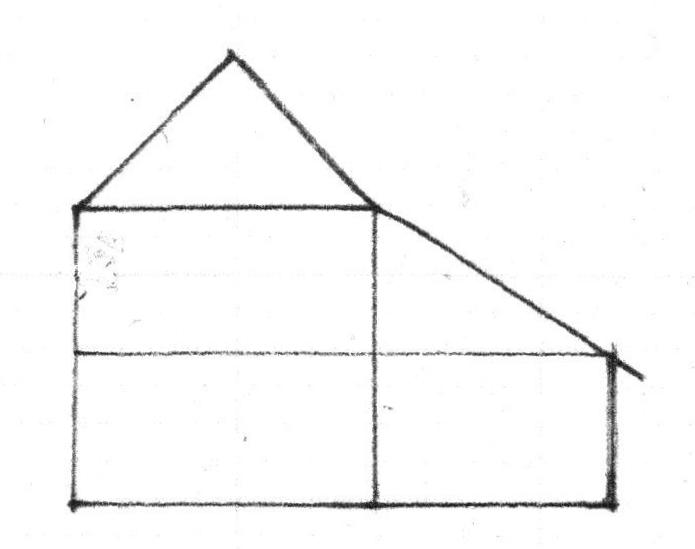
Note that while in a diagram the roof would meet an 8 ft deep and 8 ft high room at the upper far corner, in reality the width of the posts and beams and rafters often made for a lesser height.


The back wing was useful. It often was 10 feet deep.  The diagram shows how the roof pitch changed. If the lean-to were added after the main house was built, the rafters might join the frame under the roof. That would also lower the roof pitch. 


Here is the window placement;  all are centered on their interior spaces.


The photograph at the beginning of this post shows how owners adapted and updated the basic house. More windows were added on the sides. The front windows were sometimes enlarged. Columns and an architrave with molding were added to the front door. After 1780 front entries were added to many houses.


The rhythm. pattern, proportions - the geometry, including the window sizes, of a Georgian saltbox came from its construction, the available materials, and its function. It used timbers and hand tools to create shelter. It did not need to accommodate bathrooms or closets, nor provide much privacy. I think a modern saltbox, built with modern materials and tools for 21st Century life, will need its own rhythms, patterns, and proportions.


This is Abbott Lowell Cummings' first illustration in his pamphlet, showing the frame I have laid out  - a center chimney with a room on each side on each floor.


The main floor plan shows how the lean-to was added and used.  This plan, common on the New England seacoast, came with settlers to western Massachusetts,Vermont, and upstate New York. It is often inside what appear on the outside to be Federal and Greek Revival houses.  The chimneys move, the ceiling are taller, the stairs more gracious, but the floor plan remains.


Abbott Lowell Cummings' plan is not as 'square' as my diagrams. Here is the geometry. The Hall on the right is a square room. The dashed red arc is the width of the room transferred to the length.  

The width of the Parlor matches the Hall, but its length is shorter. It is determined by where the arcs of the width, the red dashed lines, begun at each corner of the fireplace, cross.   

The layout for the house, its rooms, begins at the chimney stack. It seems to have been placed first, the house framing against and around it.

The back wing is set true with the house using the 3/4/5 triangle which will always have a square corner,  red dotted lines. Here the wing is square, 'true', with the existing house.


* Abbott Lowell Cummings, Architecture in Early New England, Old Sturbridge Village Booklet Series, Sturbridge, MA, printed by the Meriden Gravure Company,  Meriden, CT. 1974.

 In this post I have capitalized Line because those who wrote pattern books capitalized it, and because the Line creates the design.
The name 'saltbox' was given to these houses in the late 1800's, by New Englanders who had salt boxes of  a similar shape in their kitchens. In the southern US, these roofs were/are referred to as 'cat slides'. The saltbox houses whose geometry I have studied have wonderful variations and quirks. Often these are due to the changes in  fireplace, bake oven, smoke chamber, flue, and chimney construction technology. 

The photograph of the Kimball House comes from the archives of the Andover Center for History and Culture. 


Saturday, June 25, 2016

The Persistence of the Salt Box Plan, Part 2

The original owners of these houses in Bennington County, Vermont, have ancestors who lived on the New England seacoast. 

Why is that useful information? 

Settlers built what they knew. 
We have seen this in the houses the Dutch built in New Amsterdam, in the Victorian era houses in Oregon which look like the 1840's houses on the East Coast their owners had left behind, in the houses in Ohio's Western Reserve which copy those their owners knew in their home towns on the Connecticut River. 

House-wrights in new settlements built what they had been taught 'back home'.  They might have seen a pattern book; but those guides showed the Classic Orders, complex roof details, stairs and railing, mantles and entrances: decoration - not basic post and beam framing systems. A house-wright learned his craft by apprenticing to a master-builder: hands-on. He built what he had been taught and had seen.

Bennington County house-wrights copied the saltbox plans they knew.

Here are two examples.

Samuel Safford came with his family to Bennington, VT, in 1761. The next year he built the town's first corn mill and a saw mill. In 1769, he built this house for his family, 2 stories with a tight front stair against the center chimney, a large room on either side, a long narrow kitchen behind with small service rooms on either end - the salt box plan. The Safford family had lived in Hardwick. MA. Their parents had lived in Ipswich, MA. Houses with this floor plan, pre-dating this one in Bennington, can easily be found in both towns.

The Safford Mills Inn is now a B&B and a restaurant, open to the public.


The house where Robert Frost wrote 'Stopping by Woods on a Snowy Evening" is also open to the public. It is a museum in Shaftsbury, VT.

Built by Amaziah Martin in 1769 it uses the salt box floor plan with a variation, a center hall. The chimneys were located on the end walls which are stone.
Martin was part of a group of Baptists who came to Shaftsbury about the same time that Bennington was being settled.
The Baptist families came from Dover Plains, NY. Their parents had come to Dover Plains from the area around Smithfield, RI, where there are many salt box houses. 

Both of these houses were dramatically updated several times in the last 240 years. For an architectural historian - me - they are fascinating to visit.

I have researched the family lines for the Saffords and the Martins. I think it adds little to my thesis to include those genealogies here. 


https://www.jgrarchitect.com/2016/06/the-persistence-of-saltbox-floor-plan.html


Tuesday, June 7, 2016

The Persistence of the Saltbox Floor Plan.


This is a ‘saltbox’. 


The name comes from its roof, which reminded Victorians of the slope of kitchen saltboxes.


Variations of this house with this roof line were built on the New England seacoast from the late 1600's to the mid-1700's..


The saltbox plan was a pattern. It did not cease to be when saltbox roofs were not longer built. It evolved, grew and adapted. 


Early NE houses were usually 2 rooms down, 2 rooms up with a chimney in the middle serving the fireplaces. 
 A lean-to off the back was often added for storage.

The storage evolved into a narrow room the length of the house with a fireplace built into the main stack. Usually small rooms on either end served as pantries and bedrooms for birthing or invalids. 


The drawings are by James Garvin - please see citation at the end of this post.


Settlers moving into Maine, western Massachusetts, the upper Connecticut River valley, and across the Green Mountains of Vermont built what they remembered - the layout, the relationship of rooms to function and each other. 


Sometimes they grew the house, using the salt box floor plan for a wider cape. This also simplified the roof frame. 


James Breckenridge built this cape in Bennington, VT, about 1765. 


This c.1800 cape, the house end of an attached farm complex, is near Brunswick, Maine. 


Bennington framers were influenced by their proximity to Dutch framing systems in the 
Hudson River watershed.
They  built story-and-a-half capes with more head room upstairs. The first floor was the saltbox  plan: 2 main front rooms with smaller rooms in the back. So was the second.


Hezekiah and Ira Armstrong built this farmhouse in Bennington  about 1810. Although it has been updated by its 5 subsequent owners, its original floor plan is still clear. 


A  story and a half cape with a post and beam frame, now demolished, about 5 miles from the Armstrong House. 

The original plan had been poorly reworked. The house lost its character.


Hiram Waters, Bennington master carpenter, built this story and a half cape for his family about 1825.

The original house uses the saltbox plan including the center chimney.
From right to left: his workshop including a display room and boarding for apprentices; his original house (the back wing with its roof facing the street); his c.1840 front wing and porch.


These 5 houses all had a steep tight back stair for access to the second floor. Broader stairs with more head room have been attempted with interesting results. 


The salt box floor plan was also used for full 2 story houses– 2 large front rooms, a long back space divided as needed on both floors,  a steep back stair as well as a turning front stair set against the chimney.
Growing up on the NH seacoast, I played in several c.1740 houses with this floor plan.


This c.1800 Westford, MA,  2 story house was measured and photographed  by the WPA in 1933-4 . It burned shortly thereafter. 


Here is its first floor plan: center chimney, 3 fireplaces, large front rooms, long back space divided as needed. 


In Bennington, VT,  the prosperous Norton family built 2 houses between 1807 and 1817 both with Palladian windows. The master-carpenter was Oliver Abel. 


These houses have center halls with graceful staircases, beautiful moldings and 2 chimney stacks. However they do not follow the 4 room, 2 chimney, center hall plan which followed the saltbox plan - seen here as drawn by Jim Garvin. They continue to use the salt box plan - 2 large front rooms, smaller service rooms in the back.


So does this house in Caledonia County, VT. first laid out about  1780, much updated since.


The Vail House in Bennington, c. 1800. While the chimneys were  moved to the end walls, the framer kept the traditional saltbox plan. 


Finally, the Blow Me Down Casino at Saint-Gaudens NHS in Cornish, NH.
I was there last week for a preservation conference. The house was part of the program.

Its record says 'Built in 1788'. At first I thought, "Absolutely NOT! Somebody who wanted to be 'Colonial' added that center chimney."


Then I looked at the paired 2nd floor windows - the placement of those windows in the wall, the geometry, said this house was pre-1800.


The record and physical evidence show that in 1926, the foundation, the first floor joists, the back wing, attic, and roof were replaced. East and west windows were altered. The chimney was removed, rebuilt. Again in the 1950's the first floor interior was changed. Porches, verandas, balustrades were added and deleted. 


I explored the house, basement to attic. I read the drawings and notes. One indicated the 2nd floor layout had been adapted, not changed.

Not until I had left the conference did I realize the 2nd floor was the saltbox layout -  a large front room on either side of a center chimney, (now removed and replaced by a bathroom and modern chimney) perhaps a front stair (now also gone) and the back stair in the back wing with small secondary rooms. 

For more , please read my second post on the saltbox floor plan: https://www.jgrarchitect.com/2016/06/the-persistence-of-salt-box-plan-part-2.


To read about the house first pictured  - the Defoe- Mooar- Wright House in Pownal, VT, - see the column I wrote for the Bennington Banner. http://passingbyjgr.blogspot.com/2015/03/the-defoe-mooar-wright-house.html

Most of the houses shown here I have been in, including their basements and attics. Many I have measured. They all have the saltbox floor plan. I have posted photographs to emphasize that the exterior style of a house was not necessarily reflected in the arrangement of its spaces, and to show the persistence of the saltbox plan.


The 3 floor plans are drawn by James L. Garvin, and can be found in his book, A Building History of Northern New England. Hanover and London, 2001. p.97,98,99. They are reproduced here with his permission.

I am not the only person aware of this persistence of form.

Kenneth Hafertepe, in his article  Asher Benjamin Begins: the Samuel and Dorothy Hinckley House in Old-Time New England, Spring/Summer, 1999, mentions on page 8 that in the Connecticut Valley "center chimneys persisted into the next (19th) century". Benjamin built the Hinckley House in Greenfield, MA, in 1796. 
http://www.historicnewengland.org/preservation/your-older-or-historic-home/articles/pdf523.pdf


Sunday, January 19, 2014

The French Andrews House Geometry - Part 2 of 2

The geometry of the floor plan of the French Andrews house focused on the fireplace and chimney mass. Two squares determined the space and the surrounding post and beam frame.  (See Part 1)
Did the framer used the same pattern on the elevations.
He did.
The red squares in the center of the front elevation show this. Starting from the stone foundation, the width of the firebox is also the height to the 2nd floor - the location of the 2nd floor beam. The square above determines the attic floor - the placement of beam at the eaves. The top of the third box is at the height of the ridge pole.
Both sides of the front elevation are squares with one longer side determined by the radius of the circle which fits around the square.  For clarity I have only drawn the square with its diagonals on the west side and I have only drawn the arc in question, 1/4 of the circle.    


 The east and west elevations are identical except that the location of the 1st floor door shown here is the location of a window on the east side.
Again the square is the determining geometry. I could have overlaid my red squares in several different patterns which all worked. I chose this one because it shows how the arc hits the center of the window, the center of the original house, and the edge of the square is also the edge of the door frame.
The north side of the west elevation is a duplicate, reversed, of the one shown. Again I didn't draw it so that the pattern would be easier to read.


 This is a geometry for framing. The squares lay out beam and post locations, not necessarily walls and room sizes.

I wondered how the lean-to was laid out, especially since it was added later and its floor plan used the 3-4-5 triangle, not squares, so that the wing would line up squarely with the existing house.
The lean-to elevation is also laid out with squares, but these begin not from the foundation, but from the first floor - which makes sense  - it was a given.

The roof pitch surprised me because it is so obvious: the diagonal through 2 squares. Given the pattern already established it came naturally and is steep enough when shingled with wood shakes to keep out the rain.

Sometimes when I see these patterns emerge I shake my head and look at myself askance, "Of course! What else would have worked so easily?"

 On the second floor plan are dotted lines indicating the exposed beams overhead. Using my calipers I scaled them and found they made a square. They are not the dimensions of the 'chambers' - they mark the outer edges for the placement of the posts and beams.
Next, drawing the arc based on the length of the square I marked where the arc crosses the diagonal - the Golden Section. All the windows in the south elevation (except the one above the front door, see Part 1) are placed by the Golden Section. The windows are not centered by the Golden Section as they would be a few decades later. Instead the line marks the side of the window. It tells the carpenter where to start to frame the window opening.

Enjoy how the stair hall space within the beams is also a square, although the hall itself is slightly wider as the walls have been placed on the other edge of the beams.

Sunday, January 12, 2014

The French- Andrews House geometry, Topsfield, MA - Part 1 of 2

updated 1/ 2019: the geometry is not the Golden Section. It is the square and its diagonal which I have found in many later houses.


When I was thinking about the original salt box shape of the Locke Tavern, I looked at other early Georgian saltboxes I knew for a comparison.
I thought I would find a similar geometry that would reinforce what I had already seen. Instead I found another way to use squares and the circles that fit around them to organize a frame.

This house I have only seen from a distance. However, measured drawings for it are available on HABS. And
a website for the French Family includes many pictures and a time line.

http://www.loc.gov/pictures/item/ma1015.sheet.00002a/resource/
 www.frenchfamilyassoc.com/FFA/ARCHITECTURE/Topsfield.htm

The French Family site says the house dates to 1675. The HABS drawings, done for SPNEA ( now Historic New England) in 1933, say 1710. Abbot Lowell Cummings says 1718. In any case it predates the Locke Tavern, and it was built in the same neighborhood.
Here is what I can see about its construction by looking at its geometry.


 Notes on the drawings for the second floor say at the wall between the lean-to and the upstairs bedrooms: "rear wall old weathered clapboards... balance of wall is shingled". This means the lean-to was added; the exterior siding left in place. I have seen this in other early houses. It is not unusual.

It does mean that the front of the house, the chimney, the hall and the chamber were built first.

The geometry for the main house is the square and its diagonal. The entry and chimney block consisting of 2 squares (red x's in the center) The corners would be the location of posts and bearing for the summer beams - the beams which are in the center of the rooms.
The size of the rooms is determined by the extended square and its diagonal (dotted red line showing the square and the diagonal).

The front door is not centered. For a while I thought this might mean one side of the house was built before the other. But then I realized that for the door to swing fully open it had to be off-centered, and that I had seen this layout in other early small houses.
You can see in the elevation that the hall window above the front door is also not quite centered - but carefully placed to minimize the asymmetry so that it would not apparent at first glance.
Here I have to stop and appreciate the builder who understood how far off from the center of the door and then, from the spot equidistant between the 2nd floor windows he could position the window where it would least call attention to the discrepancy. A fine mind there, one which speaks to me today. He succeeded.
Now in January 2019, I am wondering if he framed the wings after the chimney block was determined, as the Parson Capen House seems to have been. This would mean the window geometry came first, the door location last.
 

The lean-to dimensions were determined by the 3-4-5 triangle (the green triangle on the plan).
This made the framing square to the house - the joists, purlins and sheathing would fit neatly, the house would be tight.
From the drawings we can tell that the width of the house was already 45'-6". The depth of the house became 34'-6".
45.5' divided by 4 is 11.375'.
34.5' divided by 3 is 11.5' .
Was the master carpenter 4+" off? Maybe. But I do not know from what place he began his dimensions - the foundation? the outside of the frame? the outside of the sheathing?
Perhaps the house shifted in 200+ years between its construction and  its measuring, or was re-sheathed. And the measurements might be 4" off.


Saturday, January 4, 2014

The Locke Tavern, once a saltbox - Part 4 of 4

During the recent updating of the plumbing  for the Locke Tavern  the floor between the first and second stories behind the center chimney was removed.
I took this photograph standing on the first floor looking up at the exposed second floor wall between the old bathroom and the northwest bedroom while the carpenters worked around me. They were very pleased to share what they had uncovered. Here is what we saw:
* Modern plumbing running next to the chimney stack to the left as we expected.
* A diagonal beam with stud framing below and above that do not match up - ie: the beam was there before the framing.
* A door opening into the nw bedroom  - the white angle on the right.

The diagonal beam is the beam for the original roof over the back wing .
On the top edge of the beam you can see where the purlins were let in. Over that would have been laid the sheathing and then wood roof shingles.


The Locke Tavern once had a lean-to back wing. The space was served by a third fireplace set against the chimney block.
This house shape is referred to as a 'salt box'.
Sometimes these wings were added later, the new roof laid over the existing one, often at a slightly different angle. I have not yet seen how these 2 roofs join.


For readers who don't know about the  form: Here is a picture of a saltbox c. 1715: the John Kimball House in Ipswich Mass. The name was applied to this way of  extending a house much later, in the 1890's. It comes from the shape of a kitchen salt box of that period. Another name for this roof configuration is a "cat slide". 
I chose this house as an example because Kimballs also lived in Andover, Mass. The picture comes from the HABS archives.


This means the northwest wing was extended and a second floor added over the lean-to when the house was enlarged and updated around 1790.

How was the size of the lean-to determined? I think the master carpenter used  the geometry of the square and the Golden Section just as he did for the main house.
 In the diagram the lean-to is outlined in black (a). The square and its diagonal extended (the Golden Section)  determine both the left and right sides (b).
The center section (c) is more problematic. I wish I had been able to photograph and  measure it on site when it was open. The drawings I am using are of the house before it was opened up. Clearly the framing extends on each side of the chimney block with the kitchen fireplace set in between. There are posts in the outside wall and posts on each side of the chimney, at the back corners of the front rooms. Maybe the shape is a rectangle that has sides determined by the 3-4-5 triangle. But I don't know precisely.

It would have been so easy if the basic floor plan were a 3-4-5 triangle! But it isn't. The house measures 36 ft x 28 ft.