Thursday, April 21, 2022

The Parson Capen House, 1683, Topsfield, MA

This post, first published in 2014, has been revised based on a better understanding of the geometry. 


Parson Joseph Capen built this house in 1683 in Topsfield, Massachusetts.  He ministered to the town from 1682 until his death in 1726.

The story about this house:  It is still here because it was owned by an old Boston family with extensive land holdings.Their herdsmen drove cattle to market in Boston along Rte 1 (which is practically next door to this house) and  used the house as a way station on their trips into the city. So it wasn't torn down, updated, or abandoned. We are lucky.

The pictures are from the LOC HABS archive. Note the drops and brackets. The windows are casements; in the picture they have been swung open.
For more information and photographs in color see  http://www.topsfieldhistory.org/parson_capen.shtml

The geometry for the house is based on the square.  

Here is how a square is derived using a compass, a straightedge and a scribe. 


 Once a carpenter knew his geometry he could layout a square in fewer steps.

The square with its arcs gives the carpenter 4 points - where the arcs cross each other - for dividing his square in half horizontally or vertically. This could have been used for the hall and the second floor beams.     


The chimney and fireplaces were to be in the middle of the house. So the builder laid out the house foundation from the chimney block. The diagram shows in the center the brick which would have formed the back wall of the 4 fireplaces  with 2 square spaces on either side: the parlor and the hall.


Next comes the fireplaces themselves, on both floors, and the flues. On the first floor the main masonry block is a square in plan, the oven needed half a square. Its flue joins the hall chimney.

 On the second floor the chimney mass is square.  


The house has 4 bents, one on each end and one on either side of the chimney mass.  The  fireplaces depths on the second floor determine where the 2 interior bents are placed. It's possible there are bents across the rooms as well. However, since the  summer beams on the first floor appear to be located over windows and the second floor beams do not match the first floor beams, I think not.
The Rule of Thirds was used to lay out the bents. It determined the heights of the floors and the placement of the windows. (The red arrows indicate ceiling heights.)

See this description for how the Rule of Thirds works: https://www.jgrarchitect.com/2020/08/lesson-6-rule-of-thirds-part-1_21.html 

The cantilevered end beams for the second floor have drops below them. The beams for the interior bents have corbels. These are quite visible in the HABS photographs. The cantilevers for the roof also have drops, as well as corbels in the middle of the roof overhangs on the end elevations.


The second floor overhangs the first floor by about a foot on the south/front side. This was popular in England as a way to protect the daub and wattle walls from rain and wind. Here weather boards - known today as clapboards - covered the frame, but the tradition continued. The attic extends out over the second floor on the sides of the house for the same reason.

These HABS photographs are beautiful and clear. Click the images to enlarge them.


The roof pitch  and the placement of the ridge pole might have been laid out from the second floor.  I have seen this proportion - the crossed arcs of the side of the square - in other First Period houses, It may have been  used here.


Note the corbel beside the 2nd floor window which supports the roof overhang.


Here is the front elevation with the drops and corbels noted. They accent the ends of the cantilevered beams which are the top plates of the bents.


The beams:
In the hall the beam which supports the second floor joists was set in the center.
The parlor, the room to the left, is larger. It needed 2 beams. So the space is divided into thirds. These beams are joined to the beam that runs between the 2 bents on this side. The windows were placed where a post would be located under those beams if they were part of bents.

On the second floor  the ceiling beam are centered. All the beams appear to be set to the side of the lines, not on the line.


This drawing may be an accurate depiction of the front elevation. However, the plans are not quite consistent with this layout.  The windows might be set equidistant from the corners of the house, or not.  They may be centered on the second floor rooms, but not on those on the first floor.

Both sets are grouped together in the same geometry. The casement windows are all the same size.


The measured drawings for the Historic American Building Survey, HABS, were done at 1/8"= 1'-0", a scale which is fine for concept, but not good enough for serious consideration of  construction details.  They have very few dimensions. The drawings from 1916 do not quite agree with HABS.
Some observations:
* The Golden Section is not used here. I find that the Golden Section is about growth; houses are about stability.
* The front door is not centered on the facade; if it were the door could not be opened back against the front wall. The brackets sit under the 2nd floor beams extended to support the cantilever.


4/21/22: I wrote much of this 8 years ago. The layout of the foundation based on the location and size of the chimney back still makes sense. I revisited the framing and the elevations, understanding that the layout begins with the framer who must decide where the bents will be; how tall;  where the marks for the mortises and tenons will be. And how will the second floor and roof cantilevers be supported? I explored how a daisy wheel might have determined the layout. The results were messy. The points were not useful markers for building this frame.


Tuesday, April 19, 2022

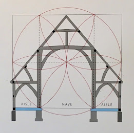
The geometrical design of Harmondsworth Great Barn, Laurie Smith

For Laurie Smith, my friend


 Here are the front and back covers of Laurie Smith's last book.


The book is full of beautiful photographs of medieval framing  and the history of the conception and construction of these barns' frames - from felling the trees to placing the aisle braces. 


Of course, as the book is about Geometrical Design, it's also is full of daisy wheels and explanations of how they were used to design the Harmondsworth Great Barn. 
Laurie Smith was a Geometer, probably the best. He researched, wrote, and taught architectural (aka 'practical') geometry.  His language and his drawings are clear and engaging. 


It is a book to read, think about, study. It can be read by a novice as well as one well versed in geometric construction. Laurie's first Drawing 1 is titled: "Names and Locations of the Frame's Timbers". It's accompanied by a Chart: "Heavy timbers needed for the barn's section". From that basic introduction he explains the geometry of the barn. 


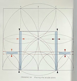
If at Photograph 39 you aren't sure what an 'arcade post' is, that first drawing is readily available. Using Photograph 39 Laurie explains how - with simple drawings, photographs, and the language of timber framing -  arcade posts, arcade plate jowls and buttresses fit together and why they are important. 

Then you understand Drawing 54.


Laurie doesn't just quote Vitruvius. He  spends time with those terse sentences in Book I, De Architectura, exploring as a Geometer, whose tools are a compass and rule, what Vitruvius means when he writes a "...plan is made by the proper successive use of compasses and rule". 


Laurie includes a carpenter's dividers, probably his own. He explains how they are 16.5 inches long, proportional to a rod which is 16.5 ft., and discusses 'stepping off'.


The geometric analysis of other great barns - The Barley Barn, Cressing Temple, Essex, and the Leigh Court Barn, Leigh, Worcestershire - is thorough and clear. 

The Notes and Credits are good reading, not a perfunctory listing of people and books. There is much here to absorb, come back to, consider again. 


Laurie finished the text, the geometric drawings, and the design in the summer of 2021. It was published that fall by Historic Building Carpentry in partnership with the UK Carpenters' Fellowship.*

He sent me a copy. I read it twice and told him how much I liked it. At his request I sent copies to a few of the timber framers in the States who had worked with him . 


I wrote that I'd put a review on my blog as I had before for his book on a barn in Devon. Here's the cover of that book.

My review is: https://www.jgrarchitect.com/2020/11/architectural-geometry-rare-geometrical.html

We enjoyed seeing that over 700 people had read that review. (now over 800)
We wondered how many had found his website through my blog post. He listed my blog on his website. I hadn't yet figured out  how to list his on mine. 
We talked about the geometry we'd  explored and learned about in the last 8 years.


Then Laurie died, December 2, 2021.

Now it's hard to read his books. I want to send an email across The Pond , "Yes, and what about....?" 

Then I remember that I read Durer, Serlio, Palladio and feel that they are speaking to me directly, 500+ years later.  Like them, Laurie's spirit is in his book. His words share his awe, his joy, and profound understanding of the geometry he saw, knew so well, and loved. 


*The Geometrical Design of the Harmondsworth Great Barn  is available through the Carpenters' Fellowship, ( https://carpentersfellowship.co.uk/) in the UK. I act as the distributor in the States. Please contact me if you would like a copy @ $25., including postage.


Friday, April 1, 2022

Images from my talk on the Historic Practice of Practical Geometry , April 7, 2022

My talk for the Traditional Building Conference in Alexandria, VA, focuses on the geometry we used before and sometimes after we had standardized dimensions. I mention many pattern books and their authors with only brief introductions.

I have added links here to my blog posts that explore and add context to these ideas. I will add more.


 Edward Shaw's book includes these engravings.
The cover of his book shows the tools of a Master Builder (an architect) and his workmen.

My blog posts on Shaw are here: 

https://www.jgrarchitect.com/2012/02/edward-shaw-uses-tools.html

This post puts him in context:       https://www.jgrarchitect.com/2019/10/portraits-of-master-builders-with-their.html

This post discusses his tools, and those of others, in detail.

https://www.jgrarchitect.com/2019/12/english-construction-tools-1669.html


 I have not explored the geometry of this door, nor the elevation below it.

These drawings with notes about the degree of roof pitch show how the Classical language of the Renaissance was no longer the standard as the Industrial Revolution began. 

Pediments  had a 4/12 roof pitch 22.5*. Now, as you can see,  maybe not.  


Perhaps the change in roof pitches was due to the availability of tin roofing sealed with lead. Before that  'roofing' was wood shingles which required at least a 4/12 (22.5*) pitch. 

Slate roofing tiles were used in the UK, and in Europe. That technology was not here until the late 1840's. 

These 3 houses I chose for their variety and visual appeal. They represent the dramatic changes in design and construction from 1860 to 1900. 

 Carpenters who had trained under Master Builders before the Civil War now became 'architects': designers who knew construction intimately and worked closely with their contractors.

Colleges began to teach and graduate people who were architects. However their drafting tools were almost identical to those used in 1750 by Master Builders.


We were still using practical geometry, and we were still passing it on as much by learning from a master trades person, perhaps an architect, as by reading about it.


Looking at these images: While I can see their geometry, I have not studied it.

The first drawings is from Woodward, George E. and Thompson, Edward G, *A Victorian Housebuilder's Guide, Woodward's  National Architect, NY, 1869.

The second is from Rossiter, E.K. and Wright, F.A. *Authentic Color Schemes for Victorian Houses, Comstock's Modern House Painting, 1883.

The third is from Shoppell, R.W. et al., Turn-of-the Century Houses, Cottages and Villas, NYC, c. 1900.

 The * indicates a Dover Publications reprint.


The bibliography for the presentation is here: https://www.jgrarchitect.com/2022/03/a-bibliography-for-my-traditional.html