Showing posts with label regulating lines. Show all posts

Thursday, April 21, 2022

The Parson Capen House, 1683, Topsfield, MA

This post, first published in 2014, has been revised based on a better understanding of the geometry. 


Parson Joseph Capen built this house in 1683 in Topsfield, Massachusetts.  He ministered to the town from 1682 until his death in 1726.

The story about this house:  It is still here because it was owned by an old Boston family with extensive land holdings.Their herdsmen drove cattle to market in Boston along Rte 1 (which is practically next door to this house) and  used the house as a way station on their trips into the city. So it wasn't torn down, updated, or abandoned. We are lucky.

The pictures are from the LOC HABS archive. Note the drops and brackets. The windows are casements; in the picture they have been swung open.
For more information and photographs in color see  http://www.topsfieldhistory.org/parson_capen.shtml

The geometry for the house is based on the square.  

Here is how a square is derived using a compass, a straightedge and a scribe. 


 Once a carpenter knew his geometry he could layout a square in fewer steps.

The square with its arcs gives the carpenter 4 points - where the arcs cross each other - for dividing his square in half horizontally or vertically. This could have been used for the hall and the second floor beams.     


The chimney and fireplaces were to be in the middle of the house. So the builder laid out the house foundation from the chimney block. The diagram shows in the center the brick which would have formed the back wall of the 4 fireplaces  with 2 square spaces on either side: the parlor and the hall.


Next comes the fireplaces themselves, on both floors, and the flues. On the first floor the main masonry block is a square in plan, the oven needed half a square. Its flue joins the hall chimney.

 On the second floor the chimney mass is square.  


The house has 4 bents, one on each end and one on either side of the chimney mass.  The  fireplaces depths on the second floor determine where the 2 interior bents are placed. It's possible there are bents across the rooms as well. However, since the  summer beams on the first floor appear to be located over windows and the second floor beams do not match the first floor beams, I think not.
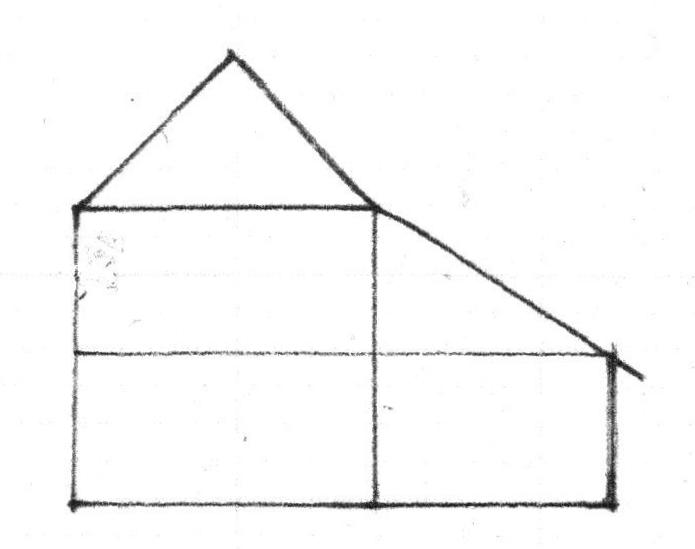
The Rule of Thirds was used to lay out the bents. It determined the heights of the floors and the placement of the windows. (The red arrows indicate ceiling heights.)

See this description for how the Rule of Thirds works: https://www.jgrarchitect.com/2020/08/lesson-6-rule-of-thirds-part-1_21.html 

The cantilevered end beams for the second floor have drops below them. The beams for the interior bents have corbels. These are quite visible in the HABS photographs. The cantilevers for the roof also have drops, as well as corbels in the middle of the roof overhangs on the end elevations.


The second floor overhangs the first floor by about a foot on the south/front side. This was popular in England as a way to protect the daub and wattle walls from rain and wind. Here weather boards - known today as clapboards - covered the frame, but the tradition continued. The attic extends out over the second floor on the sides of the house for the same reason.

These HABS photographs are beautiful and clear. Click the images to enlarge them.


The roof pitch  and the placement of the ridge pole might have been laid out from the second floor.  I have seen this proportion - the crossed arcs of the side of the square - in other First Period houses, It may have been  used here.


Note the corbel beside the 2nd floor window which supports the roof overhang.


Here is the front elevation with the drops and corbels noted. They accent the ends of the cantilevered beams which are the top plates of the bents.


The beams:
In the hall the beam which supports the second floor joists was set in the center.
The parlor, the room to the left, is larger. It needed 2 beams. So the space is divided into thirds. These beams are joined to the beam that runs between the 2 bents on this side. The windows were placed where a post would be located under those beams if they were part of bents.

On the second floor  the ceiling beam are centered. All the beams appear to be set to the side of the lines, not on the line.


This drawing may be an accurate depiction of the front elevation. However, the plans are not quite consistent with this layout.  The windows might be set equidistant from the corners of the house, or not.  They may be centered on the second floor rooms, but not on those on the first floor.

Both sets are grouped together in the same geometry. The casement windows are all the same size.


The measured drawings for the Historic American Building Survey, HABS, were done at 1/8"= 1'-0", a scale which is fine for concept, but not good enough for serious consideration of  construction details.  They have very few dimensions. The drawings from 1916 do not quite agree with HABS.
Some observations:
* The Golden Section is not used here. I find that the Golden Section is about growth; houses are about stability.
* The front door is not centered on the facade; if it were the door could not be opened back against the front wall. The brackets sit under the 2nd floor beams extended to support the cantilever.


4/21/22: I wrote much of this 8 years ago. The layout of the foundation based on the location and size of the chimney back still makes sense. I revisited the framing and the elevations, understanding that the layout begins with the framer who must decide where the bents will be; how tall;  where the marks for the mortises and tenons will be. And how will the second floor and roof cantilevers be supported? I explored how a daisy wheel might have determined the layout. The results were messy. The points were not useful markers for building this frame.


Saturday, May 1, 2021

Saltbox Geometry


I have been thinking about simple house forms and their straightforward geometry. 

I was asked about window placement for a modern saltbox. I had no simple answer.  A traditional saltbox has a door in the middle and a room on each side. The windows are evenly spaced because vernacular construction in the western world was evolving from medieval to renaissance design.  A modern saltbox?  Is it an oxymoron and if not, what would be right? That's the background. Below is the geometry for a vernacular saltbox.
 

Settlers in the Colonies included a good number of carpenters; men who had finished at least their 7 year apprenticeships. Still every family needed a house, so a straightforward plan was required; one that was easily laid out with available tools, like twine and chalk or charcoal - a Line. A carpenter square was useful, but not always truly square; it needed to be checked by geometry.  

The form that developed was a simple vernacular American house - 2 rooms over 2 rooms with a center entrance. Common all over the Eastern Seaboard, it went west with the settlers. The lean-to - its sloping roof the signature of a saltbox - was regularly added to the back, first for storage, later to expand the house.  

 
 My diagrams here are for a simple generic New England saltbox.

The carpenter needed to decide how wide, how big the rooms would be. He choose the same length for the depth and width of the parlor and the hall. That first length governed all the choices, the placement, the patterns, the dimensions that followed.

He knew the fireplaces and chimney stack would be placed in the middle so he made space for them. Then he laid out a square on one side, and another on the opposite side. This became the guide for his timber frame.


 Here is the sequence that begins with a length and ends with a square. A carpenter knew practical geometry. He knew how to use a straightedge and a Line. He had no ruler or tape measure. He probably began with the 5th diagram. He didn't need a physical compass. His Line could be pinned at one end and then swung in an arc to mark the corners. The resulting square could be checked (trued) by matching its diagonals.


My mythic carpenter choose a room depth of 16 feet. 20 feet was a common length in later houses. The diagram is to scale; it is 16 ft. deep and 40ft. wide.  I have allowed 8 ft. for the fireplaces and chimney. 


The same square - 16 ft. x16 ft. - was used for the height. Here it is divided in half for the first and second floors.

The ridge of the roof frame is half the height of the box - 8 feet.

Sometimes the dimensions for the framing began at the foundation. Sometimes the dimensions began after the sill was laid, made level and true. 


Here are the posts, the beams (called girts), and the rafters laid out. Next will come the summer beam, and then the joists.


For reference I am using Abbott Lowell Cummings' framing from his booklet, Architecture in Early New England. His first diagram is entitled "Typical framing details.." . The second, "seventeenth century house plan"  shows the early fireplace and chimney configurations. (see below)


The windows were centered in the shape, right in the middle. Glass was a luxury in early houses; windows were small.

There might not have been one in the attic.


 Here is the diagram for easily finding the center line of the square. Swing the arc of the length as shown in the first square -dashed red lines, solid black lines. The crossing points are centered on the square as shown with the solid and dashed lines  in the second square,


The front elevation of the house was as simple as the floor plan and the side elevation: 2 squares with the chimney stack in the middle which also gave room for a stair and a entry door.

I've added shading to the roof.


The layout shows the post and beam frame, ready for the summer beam and the floor joists.  All of this could be laid out with Lines, made true and square by the diagonals, which are also Lines. A Line might be chalked to leave a mark ( a Line) on a framing floor, or it was a length of twine pinned in place by an awl, or tied to a stake.


 Here's the front elevation with  one window centered in each room.


 As glass became more available more windows were added.

There were 2 ways to place the windows using the geometry of the Rule of Thirds. Here on the left the square is divided into thirds, the windows centered on that Line. 

On the right the inside edges of the windows are on the Line. 


 Here is a diagram for the Rule of Thirds. The diagonals for the square are crossed by the center line. Then new diagonals - red - are added to the rectangles on either side of the center line. The diagonals of the square cross the diagonals of the rectangles at points which divide the square into thirds.

I have only shown the square's diagonals and the red diagonals in the drawing which shows window placement.  The square with all its Lines can be visually overwhelming.


This diagram shows the squares divided into thirds - the dashed lines. On the left the windows are placed on the center line - dot-dash lines. On the right the inside edge of the window is on the Line -  solid lines

In a new community settlers from different areas  brought different framing traditions. 2 houses side by side might use different patterns, reflecting the carpenter's background.


The lean-to was an obvious expansion: just an extended roof covering the new space. The space did not always include a fireplace. When a fireplace was added it was laid up against the existing masonry.

 Here is the diagram  showing the carpenter's Lines.

Note that while in a diagram the roof would meet an 8 ft deep and 8 ft high room at the upper far corner, in reality the width of the posts and beams and rafters often made for a lesser height.


The back wing was useful. It often was 10 feet deep.  The diagram shows how the roof pitch changed. If the lean-to were added after the main house was built, the rafters might join the frame under the roof. That would also lower the roof pitch. 


Here is the window placement;  all are centered on their interior spaces.


The photograph at the beginning of this post shows how owners adapted and updated the basic house. More windows were added on the sides. The front windows were sometimes enlarged. Columns and an architrave with molding were added to the front door. After 1780 front entries were added to many houses.


The rhythm. pattern, proportions - the geometry, including the window sizes, of a Georgian saltbox came from its construction, the available materials, and its function. It used timbers and hand tools to create shelter. It did not need to accommodate bathrooms or closets, nor provide much privacy. I think a modern saltbox, built with modern materials and tools for 21st Century life, will need its own rhythms, patterns, and proportions.


This is Abbott Lowell Cummings' first illustration in his pamphlet, showing the frame I have laid out  - a center chimney with a room on each side on each floor.


The main floor plan shows how the lean-to was added and used.  This plan, common on the New England seacoast, came with settlers to western Massachusetts,Vermont, and upstate New York. It is often inside what appear on the outside to be Federal and Greek Revival houses.  The chimneys move, the ceiling are taller, the stairs more gracious, but the floor plan remains.


Abbott Lowell Cummings' plan is not as 'square' as my diagrams. Here is the geometry. The Hall on the right is a square room. The dashed red arc is the width of the room transferred to the length.  

The width of the Parlor matches the Hall, but its length is shorter. It is determined by where the arcs of the width, the red dashed lines, begun at each corner of the fireplace, cross.   

The layout for the house, its rooms, begins at the chimney stack. It seems to have been placed first, the house framing against and around it.

The back wing is set true with the house using the 3/4/5 triangle which will always have a square corner,  red dotted lines. Here the wing is square, 'true', with the existing house.


* Abbott Lowell Cummings, Architecture in Early New England, Old Sturbridge Village Booklet Series, Sturbridge, MA, printed by the Meriden Gravure Company,  Meriden, CT. 1974.

 In this post I have capitalized Line because those who wrote pattern books capitalized it, and because the Line creates the design.
The name 'saltbox' was given to these houses in the late 1800's, by New Englanders who had salt boxes of  a similar shape in their kitchens. In the southern US, these roofs were/are referred to as 'cat slides'. The saltbox houses whose geometry I have studied have wonderful variations and quirks. Often these are due to the changes in  fireplace, bake oven, smoke chamber, flue, and chimney construction technology. 

The photograph of the Kimball House comes from the archives of the Andover Center for History and Culture. 


Sunday, April 5, 2020

PRACTICAL GEOMETRY - Lessons 2


The posts in this series  Lessons 1-7  are :

 https://www.jgrarchitect.com/2020/04/lessons.html

 https://www.jgrarchitect.com/2020/04/practical-geometry-lessons-2.html

 https://www.jgrarchitect.com/2020/04/practical-geometry-lesson-3.html

 https://www.jgrarchitect.com/2020/04/practical-geometry-lesson-4.html

https://www.jgrarchitect.com/2020/04/practical-geometry-lesson-4b-old-first.html

https://www.jgrarchitect.com/2020/06/practical-geometry-lessons-lesson-5.html

https://www.jgrarchitect.com/2020/06/practical-geometry-lesson-5-addendum.html

https://www.jgrarchitect.com/2020/08/lesson-6-rule-of-thirds-part-1_21.html

https://www.jgrarchitect.com/2020/08/lesson-6-rule-of-thirds-part-2-serlio.html
 
https://www.jgrarchitect.com/2020/09/lesson-7-how-to-layout-frame-with-lines.html

Saturday, March 21, 2020

A Barn and its Daisy Wheel


.

Not a very neat daisy wheel is it?


About 8" across, it was found during the dismantling of an upstate NY barn, c. 1790, scribed onto a board used to sheath the roof. The lines were drawn with a divider, not a marker. They can be seen in a raking light.The board is still in its proper place. This is a tracing made of the pattern carved by the pin of the divider.


The barn is probably the first of 4 connecting barns, c.1790. Green Mountain Timber Frames recently dismantled, repaired, and sold this barn for reuse.


It has modified gunstock posts, a 5 sided ridge pole, rafters spaced 38" on center.


The daisy wheel determined the framing layout.

The petals are the arcs of the radii. The points of the petals divide the circumference and locate the diameter. The sheathing board with the daisy wheel was a template, the reference for lengths and relationships. When it was no longer needed it became sheathing.

The master carpenter could rotate the daisy wheel first with one diameter  vertical and then with one diameter horizontal. He could use all 12 points and spokes. The radius and the distance between each point are the same length.


So how did the carpenter begin? He and the farmer knew the approximate size and location of the proposed barn. He decided on a width (the radius of his circle) and drew his daisy wheel.

Using the points on the circumference and a line, he marked the width and the rectangle of the circle  ( the 'x') - The green dashed lines show how he determined the length of the barn. The dashed red lines show the floor plan . 


The farmer wanted an English barn with a center door. The door needed to be a certain width for easy movement. 
Was 32' long enough? Would a 12' wide door give him enough working space on either side of the door? Would a 12' high wall work?  If that 12' were also the height of the barn wall there would be enough space for a lintel at the top of the door frame for strength. And what size are his timbers? 


He decided 11'-2" was wide enough, 12'-4" tall enough. The
carpenter laid out the door within the circle.
The width of the door is the radius of the circle, and the height of the barn wall.
The square laid out by the arcs of the radius.


The placement of the door lintel is set at the crossing of the arcs of the radius.


Since the door is in the center of the wall, the right side mirrors the left.  The arcs  - dashed red line -  locate the center of the circle to the right. 
The right side could also have been stepped off with a large compass.


The interior bents of the barn fit neatly into the daisy wheel geometry. The rectangle is laid out by the division of the circumference into 6 equal parts. The dashed red line shows the rectangle of the daisy wheel. While the layout of the barn is a traditional English pattern, dropped beams are the regional Anglo-Dutch vernacular tradition. They are placed using the same geometry as the lintel.


The end elevations fit into the daisy wheel too. Of course! interior and end bents need to be the same size. The plates are not dropped.

This is the first pattern I saw when I began to study how this daisy wheel was used in this barn. I thought the layout began here.
I now think he began, not with this simple end bent, but with the door.


The gable's ridge is 22' high.  22' is also the width of the bent, the side of the square which enclosed the gable end.

The roof pitch was determined by a square using the width of the barn as the dimension.
A carpenter used a framing floor to lay out his bents, mark his mortises and tenons.  This bent could have been laid out on the dirt floor of this barn using twine the width of the barn.   


The daisy wheel was the design for the barn. The carpenter knew how to use it.
The specific 8" daisy wheel probably was the dimension - measured across the diameter - used to locate the holes for the peg: they are all at 32" 4 lengths of the daisy wheel diameter.  The distance between holes for pegs on the braces appears to be 48", 6 lengths. 
Today I have no way to check this. I hope I do in the future.


3/21/2020: This post is a complete revision of a post I first wrote in 2014. 


 .