
The original house is the front (left) section: 2 rooms up and down, each with a fireplace. The chimney in the middle served all the fireplaces and acted as a radiator.
The saltbox extension was added c.1720. The rear wing dates to the 1950's.
.jpg)
John Abbott measured and drew the floor
plans and elevations of the house for HABS in 1934. At that time it was thought that Simon
Bradstreet had lived here. Now we know the families of the Reverend
Thomas Barnard and his son, the Reverend John Barnard, were the first
residents from 1715 to 1757.
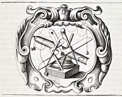 Here are the tools a Massachusetts Bay Colony carpenter had in 1715 for planning and laying out buildings*. He used a compass, a
square, horizontal and vertical levels, a straight edge marked in
regular increments (which might or might not be inches) and a line with
a spool on one end and a plumb bob on the other. The builder also had an awl, chalk,
charcoal, and an 8 or 10 ft. rod.
Here are the tools a Massachusetts Bay Colony carpenter had in 1715 for planning and laying out buildings*. He used a compass, a
square, horizontal and vertical levels, a straight edge marked in
regular increments (which might or might not be inches) and a line with
a spool on one end and a plumb bob on the other. The builder also had an awl, chalk,
charcoal, and an 8 or 10 ft. rod.Using a compass, a straight edge and a scribe a carpenter could layout the plan on a board, then step off the plan on the site with his rod or his compass, set his lines, and true them. This is the same order in which we layout buildings today; we simply use more modern tools.

This is the floor plan of the original house.
Noted in black are the sills, the posts and beams for the first floor frame .
The carpenter knew the first floor would have a Hall - on the right labeled 'living room', and a Parlor - on the left called the 'dining room'.

Between them, in the center of the house would be the chimney stack with a separate flue for each of 4 fireplaces.
Here is the chimney above the roof with articulated flues.
These spaces add up to a house about 18 ft. wide by 42 ft.
long.
The width and length of the house were stepped off with a compass or marked on a length of twine. The exterior of the house would have been staked. 3 foot units could have been stepped off 6 times for the width and 7 times for the length. Layout with a rod marked in feet would probably have been faster. A chalk line might have been snapped. Lines could have been tied to stakes for the men digging the foundation. Diagonals would have trued the foundation. All of this is similar to how we layout buildings today.
Stone foundations of pre-1900 houses tend to be vertical on the inside of the wall, the basement side, battened into the soil on the exterior. 2 lines would be required to accurately set the top of the foundation - where the sill would sit, where the outside wall of the house would stand.

The length of the beams of the frame, approximately 18 ft., probably determined the house width.
The Hall, the biggest room, was a multi- purpose room, used for cooking, chores, gathering. Often set in the southeast corner of the house, it had sunshine from early morning to late afternoon. Here the room is square with a beam to support the 2nd floor across its center. The arc of the 18' width locates the posts.
Note that the dimensions appear to begin at the inner side of the right hand posts, indicating that while the exterior of the foundation was laid 18 ft. x 42 ft., the layout for the timber frame appears to have been set from the sill and those first posts.
Laying out the geometry from the inside of the frame would have been a practical choice. The sills would not cover the line, but located beside it. Truing a rectangle by checking its diagonals to the outside corner of a post would be tricky, especially after the posts were in place. The framing timbers also needed to set to the line. And, the outside of a stone foundation could be irregular - as field stones are - without compromising the bearing of the frame on the foundation.
This length, this inside dimension, would also have been the one the framers used to lay out the mortise and tenon joints on the beams.
.jpg)
The entry and staircase fit into the leftover space in front of the stack.

The Parlor, the room to the left, was used for business and formal occasions, to welcome and entertain visitors. Sometimes it was also the master bedroom.
It was smaller than the Hall and also had a centered beam. The arcs cross at the outside edge of the wall, setting the width of the room.
 The length of that width could easily be measured from the
layout of the Hall. Here the arcs cross, giving 2 points for drawing a
line which, extended, is the width of the Parlor. Note the black line with arrows.
The length of that width could easily be measured from the
layout of the Hall. Here the arcs cross, giving 2 points for drawing a
line which, extended, is the width of the Parlor. Note the black line with arrows.
Yes, if the line which measured the width of the square of the Hall had been folded in half and marked, it also would have given the point needed to determine the width of the parlor. In either instance the framer needed to understand the geometry. Geometry was a tool. It was practical. It is also why the proportions of these buildings are graceful; why they speak to us.

The Parson Barnard House, seem from its front garden in 2022.
Note that the geometry of the house is so strong that the front door of the house seems to be in the middle of the facade. Actually the right side is wider than the left side. The windows on the left are closer together than those on the right and the wall spaces between the door and the windows on either side are not equal.
The geometry of the frame and the elevations will be another post.
* the image is the frontispiece for Giancomo Barozzi Da Vignola, *Canon of the Five Orders of Architecture, translated by John Leeke, published by William Sherwin, 1669.
.jpg)
.jpg)
** A square can be laid out by a compass. Square corners can be determined and proved by a daisy wheel. Here is the visual explanation: the width A-B as the radius of the circle and locates the 6 points of the circumference A, B, C, D, E, F, G. Then: Lines A-F and B-E are perpendicular to A-B. Line G-C locates the end (west) wall of the Parlor.
For more information and a tutorial see: https://www.jgrarchitect.com/2023/01/geometry-in-construction-practical.html
1 comment:
Jane,
Thanks much for posting this. It's always a delight to walk through the geometry behind these
historic buildings. After you pointed out that the front entry door and front elevation is
not symmetrical, I paused and looked closer. Actually think this offset wrinkle adds a bit
of something to the aesthetic. Think I like it better than if it had perfect symmetry.
George
Post a Comment